SWRU630 December 2024
- 1
- Description
- Getting Started
- Features
- 1Evaluation Module Overview
-
2Hardware
- 2.1 xWRL6844EVM Antenna
- 2.2 EVM Mux Block Diagram
- 2.3 Switch Settings
- 2.4 Push Button Switches
- 2.5 LEDs
- 2.6 DC Input Jack
- 2.7 USB Connector
- 2.8 DCA1000 HD Connector
- 2.9 BoosterPack Connector for LaunchPad Connectivity
- 2.10 CAN-FD_B Connector
- 2.11 CAN-FD_A Connector
- 2.12 LIN-PHY Connector
- 2.13 I2C Connections
- 2.14 XDS110 Interface
- 2.15 FTDI Interface
- 2.16 DCA1000EVM Mode
- 2.17 PCB Storage and Handling Recommendations:
- 3Software, Development Tools, and Example Code
- 4Hardware Design Files
- 5Additional Information
- 6References
- 7Revision History
2.11 CAN-FD_A Connector
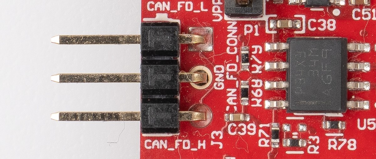
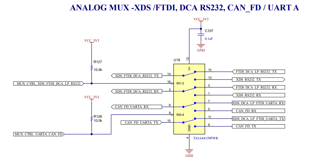
The J3 connector shown in Figure 2-21 provides the CAN_L and CAN_H signals from the onboard CAN-FD transceiver (TCAN3403DRQ1). These signals are wired to the CAN bus after muxing with the UART-A signals; one of the two paths must be selected. CAN signal paths get connected to PHY by changing the switch S1.4 to off position. CAN standby input can be controlled by toggling S4.1 switch.
 Figure 2-21 CAN-FD A Connector
 Figure 2-22 Analog Mux for the CAN PHY
Switch
 Figure 2-23 CAN-FD PHY Used in the
EVM