SWRU636 December 2024
2 Software Quickstart Guide
The following is a step-by-step overview to get the Out of Box demo running on the xWRL6844 device.
Install Software
To get started, install the latest version of the mmWave Low-Power SDK 6 and the EVM drivers:
Setup Demo Hardware / Software
Connect to EVM via the micro USB port at bottom right of board labeled XDS_USB. You do not need to connect to the barrel jack.
Navigate to the MMWAVE-L-SDK download location and run the mmWave Radar Visualizer. The visualizer is located at <MMWAVE_L_SDK6_INSTALL_DIR>\mmwave_l_sdk_06_00_02_00\tools\visualizer\visualizer.exe.
Flash Application Binary
Open the "Flash" tab in the visualizer and select the COM port of the EVM. It should be automatically detected. If not, look for the "XDS110 Class Application /User UART" COM port in your Device Manager, and select this port in the GUI. (Note: If you don't see the correct COM ports in the Device Manager, you need to install the XDS110 drivers listed in step 1 "Install Software" above).
Then, select the xWRL6844 in the drop down. It should be automatically detected.
Place the device into flashing mode by setting the switches as shown in the visualizer.
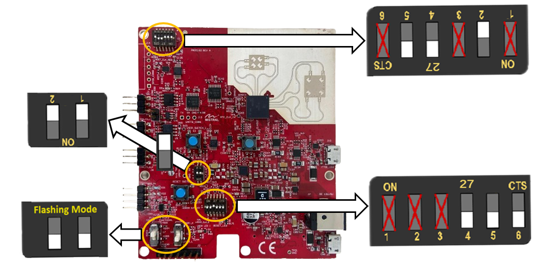 Figure 2-1 Flashing mode switch settings.
 Then, press the Reset SWITCH/button to register the SOP settings. Reset button is labeled "RESET SWITCH".
Finally, press "Switch Settings Confirmed" in the visualizer.
 Figure 2-2 Confirm switch settings button.
 Select the desired device binary. The "Range-Doppler Image" (mmwave_demo.release.appimage) is the Out of Box binary. Also, custom binaries can be uploaded here.
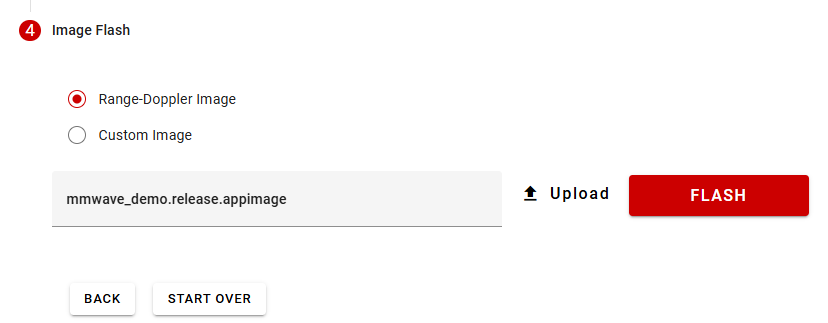 Figure 2-3 Image flash options.
 Select the "Flash" button. Upon a successful flash, you will receive a message that flashing was successful.
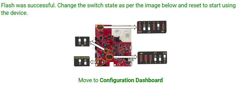 Figure 2-4 Successful flash.
 Change the switch state as per the settings shown in the visualizer at this stage; this places the device into functional mode. Then press the Reset SWITCH/button to register the SOP settings. (Note: For more help on device setup, see Section 2.3 of the EVM User's Guide on Switch Settings.)
Send Chirp Configuration
Move to the "Configuration Dashboard" tab in the visualizer.
First confirm the COM ports and baud rate is correct. Then, under "Configuration Selection", select your desired configuration. The 4TX 4RX TDM configuration is the default configuration.
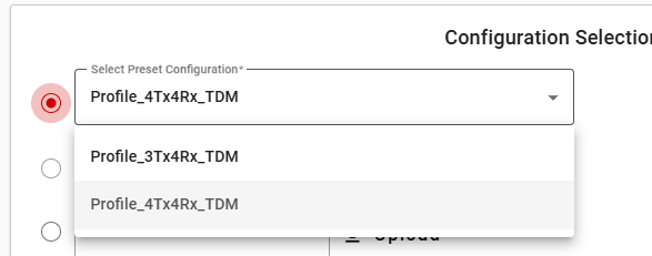 Figure 2-5 Configuration selection.
 Finally, select "Send Selected Config". (Note: CLI output can be seen in the bottom right pane)
View Plots
Once the commands are set, the Visualizer will open the "Plots" tab and display real-time visualizations of radar data.
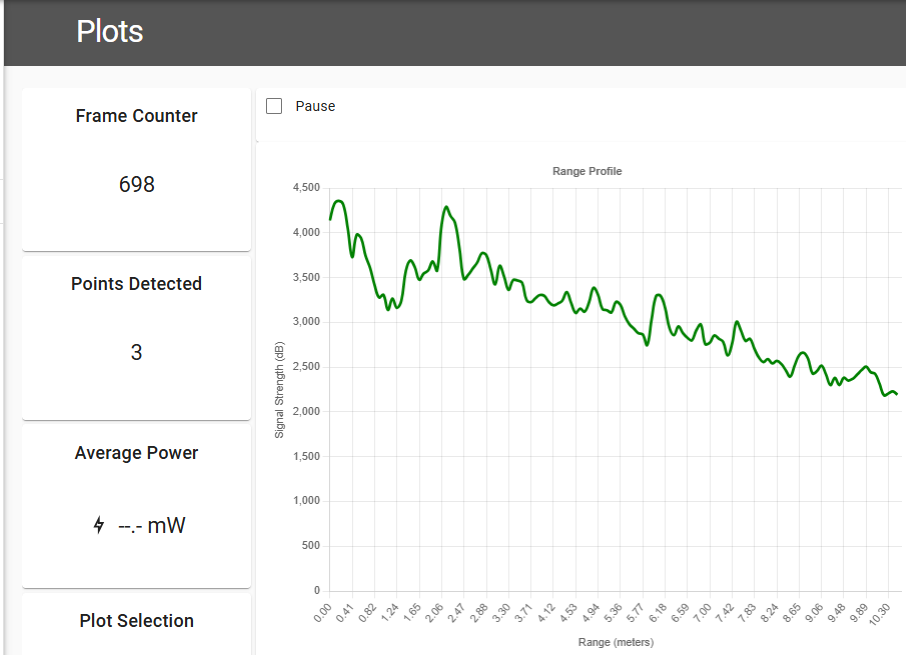 Figure 2-6 Radar data visualization.