TIDT219 February   2023


  1.   Description
  2.   Features
  3.   Applications
  4. 1Test Prerequisites
    1. 1.1 Voltage and Current Requirements
    2. 1.2 Dimensions
  5. 2Testing and Results
    1. 2.1 Efficiency Graphs
    2. 2.2 Efficiency Data
    3. 2.3 Thermal Images
    4. 2.4 Bode Plots
    5. 2.5 Electromagnetic Interference (EMI)
  6. 3Waveforms
    1. 3.1 Switching
    2. 3.2 Output Voltage Ripple
    3. 3.3 Short-Circuit Protection
    4. 3.4 Load Transients
    5. 3.5 Start-up Sequence

Electromagnetic Interference (EMI)

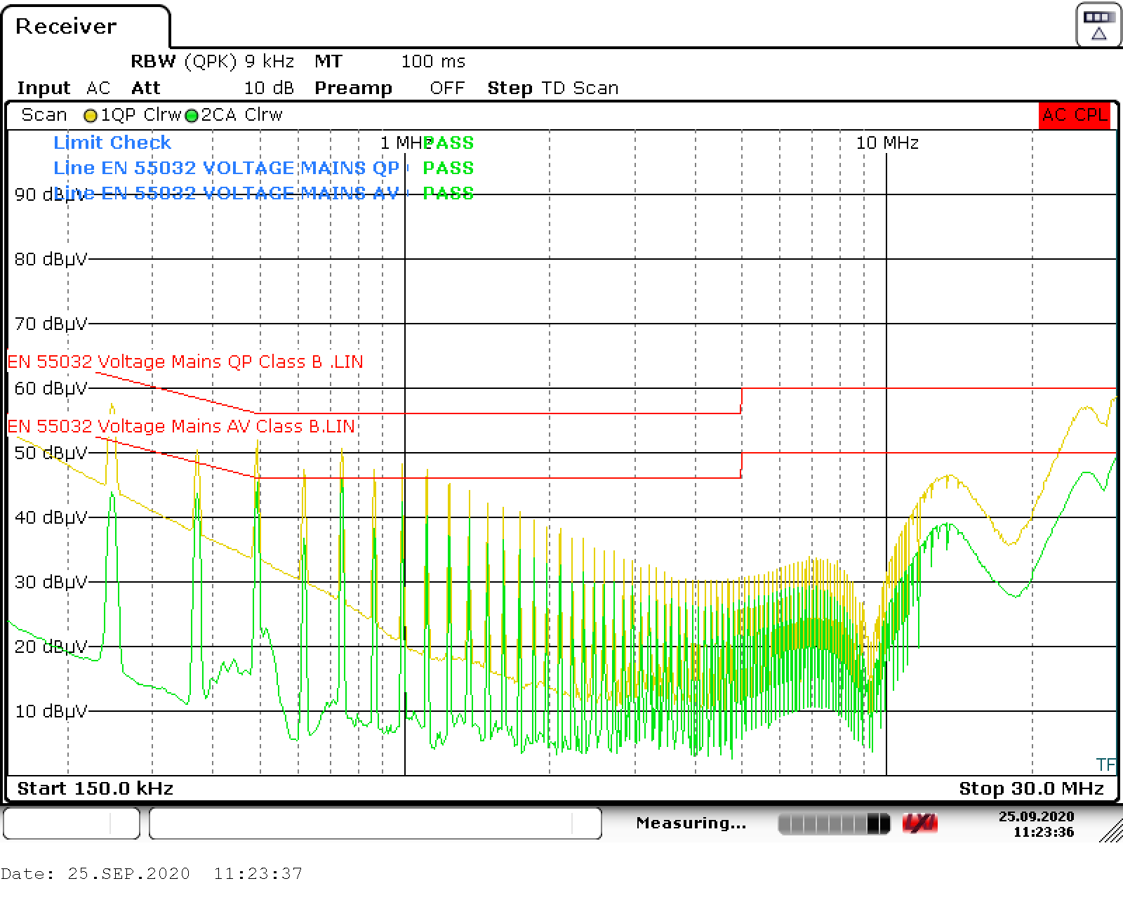
#FIG_Z3J_FHK_2MB and #GUID-B2B04398-E1A2-4E62-89D1-71FB14480486 show the EMI measured at 2300-VAC input and 24-V, 150-W output. For the tests shown in these images, the common-mode choke was moved to the bottom side of the board and a copper shield is wrapped around the transformer.
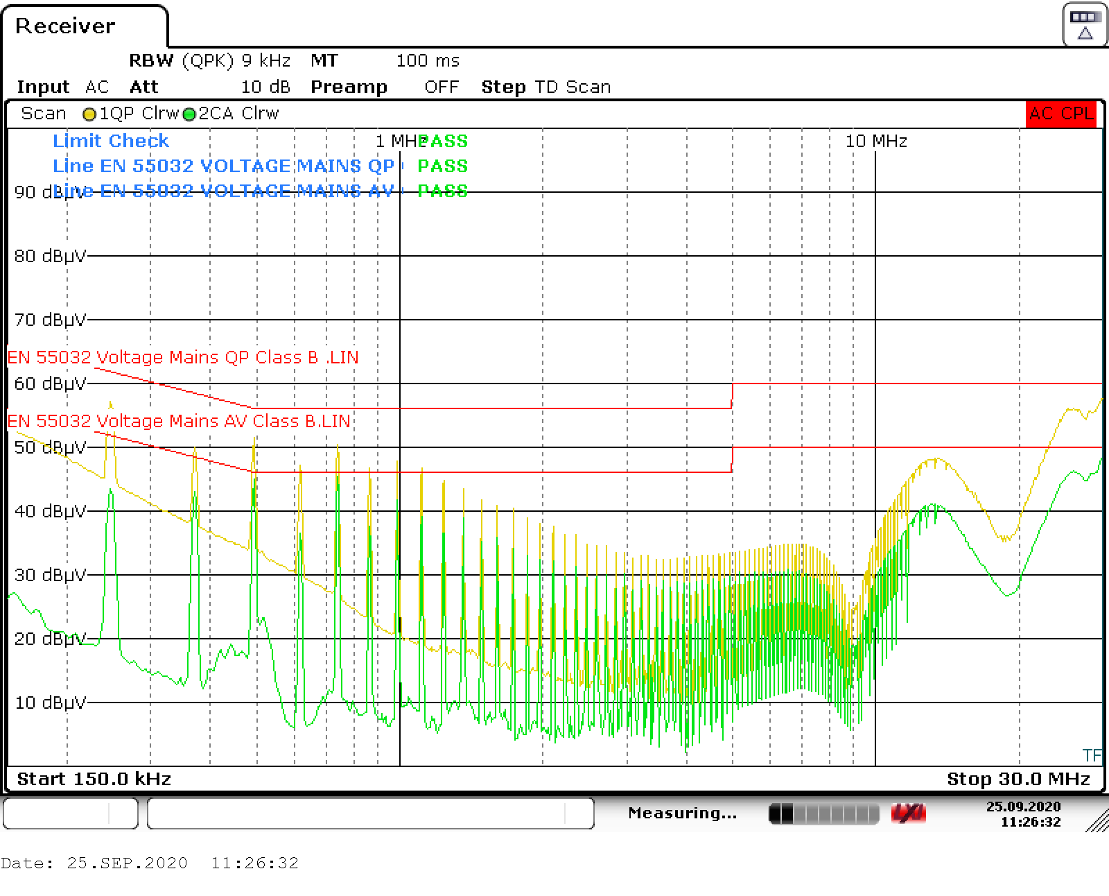
GUID-20210419-CA0I-1CTW-HXBJ-J5T7CXFRX74W-low.pngFigure 2-7 Line
GUID-20210419-CA0I-JM3P-KTR6-F3DLGTFSZPGJ-low.pngFigure 2-8 Neutral