TIDT222 April 2021
2.5 Test Setup
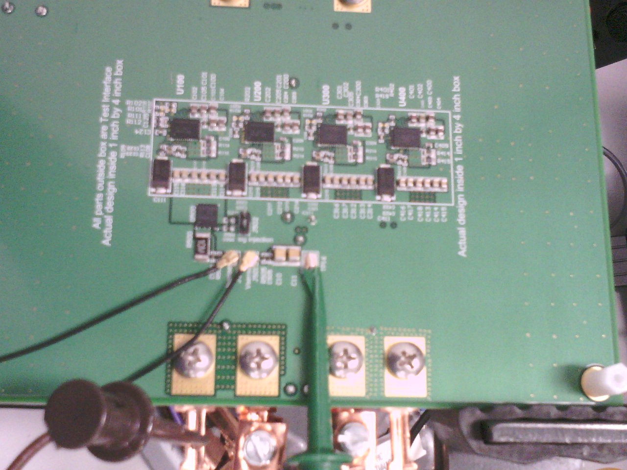
The following image shows the bottom of the board during testing. The two black cabels are used for current and voltage monitoring.
 Figure 2-1 Test Setup
TIDT222 April 2021
The following image shows the bottom of the board during testing. The two black cabels are used for current and voltage monitoring.
 Figure 2-1 Test Setup