TIDT234 November 2022
3.5 Conducted EMI Performance
The following set of figures show the conducted EMI performance of the revision B PCB running at FPWM modes at 24-V, 30-V, and 36-V inputs, at 1.2-A load conditions.
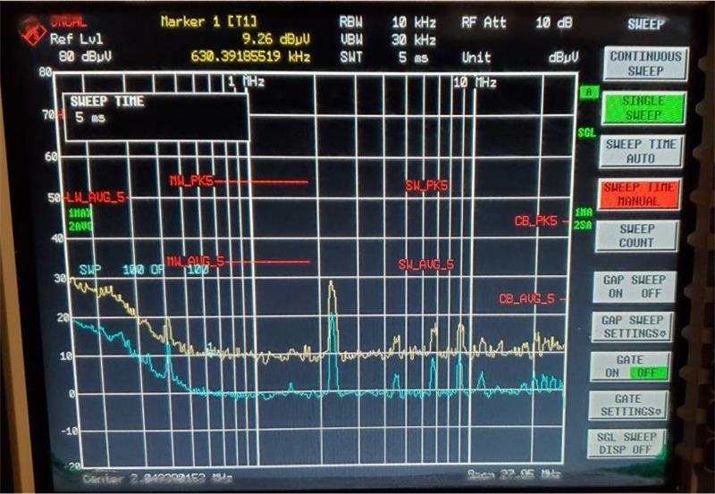 Figure 3-19 Conducted EMI Performance, 24-V Input,
Low-Frequency Range
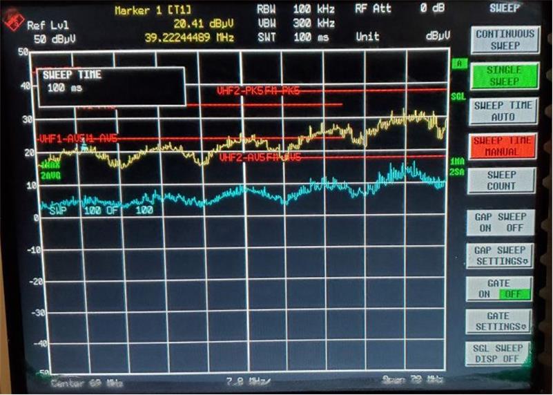 Figure 3-20 Conducted EMI Performance, 24-V Input,
High-Frequency Range
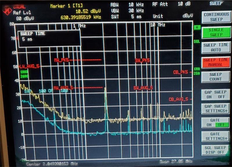 Figure 3-21 Conducted EMI Performance, 30-V Input,
Low-Frequency Range
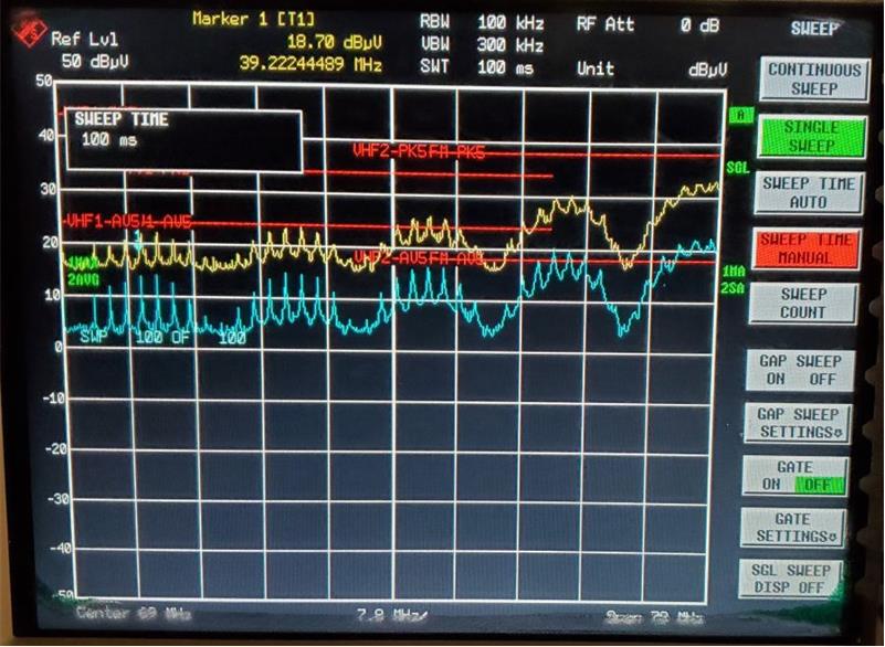 Figure 3-22 Conducted EMI Performance, 30-V Input,
High-Frequency Range
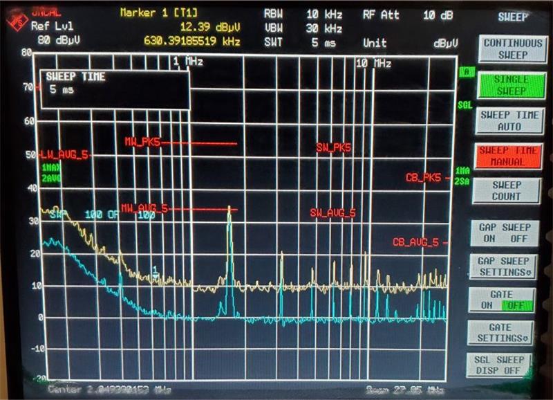 Figure 3-23 Conducted EMI Performance, 36-V Input,
Low-Frequency Range
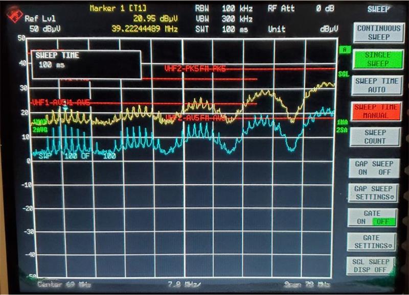 Figure 3-24 Conducted EMI Performance, 36-V Input,
High-Frequency Range