TIDT240
October 2021
1
Description
2
Test Prerequisites
2.1
Voltage and Current Requirements
2.2
Required Equipment
2.3
Considerations
2.4
Dimensions
2.5
Signal Descriptions
3
Testing and Results
3.1
Efficiency Graphs
3.2
Efficiency Data
3.3
Voltage Regulation Graphs
3.4
Cross-Loading Performance
3.5
Cross-Loading Performance Data
4
Waveforms
4.1
Switching
4.2
Output Voltage Ripple
4.3
Load Transients
4.4
Start-up Sequence
4.3
Load Transients
The following waveforms show the load transients.
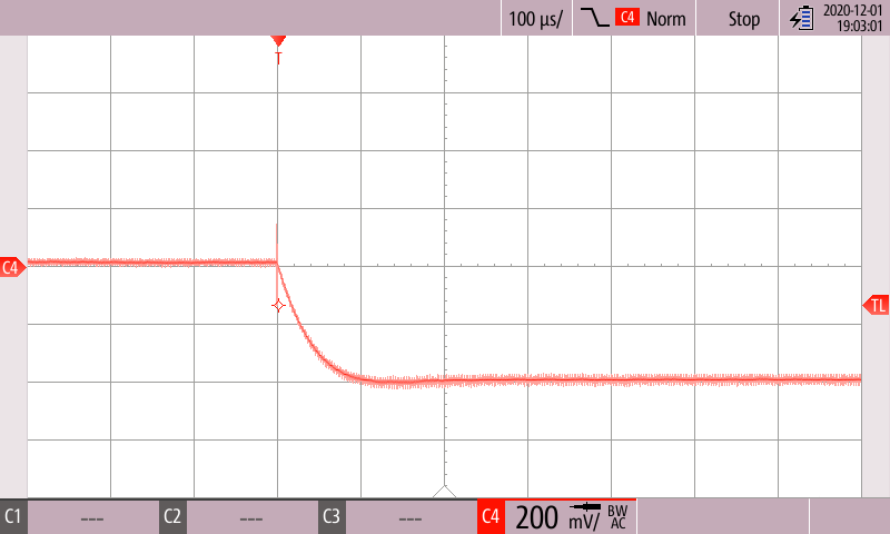
Scope Rider handheld oscilloscope with isolated channels
Figure 4-6
V
OUT1
During the Transient From 330- to 165-Ω Resistive Load
Scope Rider handheld oscilloscope with isolated channels
Figure 4-7
V
OUT1
During the Transient From 165- to 330-Ω Resistive Load