TIDT252
December 2021
Description
Features
Applications
1
Test Prerequisites
1.1
Voltage and Current Requirements
1.2
Considerations
1.3
Dimensions
2
Testing and Results
2.1
Efficiency Graphs
2.2
Efficiency Data
2.3
Thermal Image
2.4
Bode Plot
3
Waveforms
3.1
Switching
3.2
Input Voltage Ripple
3.3
Output Voltage Ripple
3.4
Load Transients
3.5
Start-up Sequence
3.6
Undervoltage Protection
2.4
Bode Plot
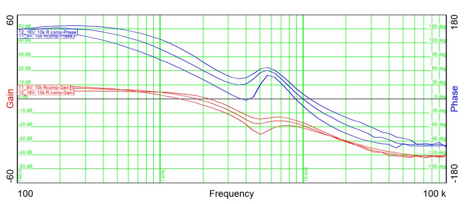
Figure 2-3
shows the Bode plot.
9.0 V
IN
, 60.0-A load current: fco 1.36 kHz, 66.1-deg phase margin, –15.81-dB gain margin
12.0 V
IN
, 60.0-A load current: fco 1.802 kHz, 67.88-deg phase margin, –19.1-dB gain margin
16.0 V
IN
, 60.0-A load current: fco 2.19 kHz, 71.37-deg phase margin, –19.1-dB gain margin
Figure 2-3
Bode Plot