TIDT262
April
2022
-
Description
-
Features
-
Applications
-
1Test Prerequisites
- 1.1
Voltage and Current Requirements
- 1.2
Considerations
- 1.3
Dimensions
-
2Testing and
Results
- 2.1
Efficiency Graphs
- 2.2
Load Regulation
- 2.3
Line Regulation
- 2.4
Thermal Images
- 2.4.1
Further Extensive Thermal
Measurements
- 2.4.1.1
No Forced Cooling
- 2.4.1.1.1
Thermal Images 4.5 VIN and 20
AOUT
- 2.4.1.1.1.1
After 1 Minute of Operation
- 2.4.1.1.1.2
After 2 Minutes of Operation
- 2.4.1.1.2
Thermal Image 5.5 VIN and 20
AOUT
- 2.4.1.1.3
Thermal Image 7 VIN and 25
AOUT
- 2.4.1.1.4
Thermal Image 9 VIN and 30
AOUT
- 2.4.1.1.5
Thermal Image 12 VIN and 30
AOUT
- 2.4.1.1.6
Thermal Image 15 VIN and 30
AOUT
- 2.4.1.1.7
Thermal Image 13.8 VIN and 30
AOUT
- 2.4.1.2
Forced Cooling
- 2.4.1.2.1
Thermal Image 4.5 VIN and 20
AOUT
- 2.4.1.2.2
Thermal Image 5.5 VIN and 20
AOUT
- 2.4.1.2.3
Thermal Image 7 VIN and 25
AOUT
- 2.4.1.2.4
Thermal Image 9 VIN and 30
AOUT
- 2.4.1.2.5
Thermal Image 12 VIN and 30
AOUT
- 2.4.1.2.6
Thermal Image 15 VIN and 30
AOUT
- 2.5
Bode Plots
-
3Waveforms
- 3.1
Switching
- 3.1.1
9-V Input Voltage (Boost Mode)
- 3.1.1.1
Boost High Side FETs (Q5, Q6)
- 3.1.1.1.1
Source-Drain (Referenced to
VOUT')
- 3.1.1.1.2
Gate-Source
- 3.1.1.2
Boost Low Side (Q7, Q8)
- 3.1.1.2.1
Drain-GND
- 3.1.1.2.2
Gate-GND
- 3.1.2
12-V Input Voltage, Transition Mode, Both Legs
Switching at ½ FSW
- 3.1.2.1
Boost High Side FETs (Q5, Q6)
- 3.1.2.1.1
Source-Drain (Referenced to VOUT')
- 3.1.2.1.2
Gate-Source
- 3.1.2.2
Boost Low Side (Q7, Q8)
- 3.1.2.2.1
Drain-GND
- 3.1.2.2.2
Gate-GND
- 3.1.3
16-V Input Voltage, Buck Mode
- 3.1.3.1
Buck High Side FETs (Q1, Q2)
- 3.1.3.1.1
Source-Drain (Referenced to VIN')
- 3.1.3.1.2
Gate-Source
- 3.1.3.2
Buck Low Side (Q3, Q4)
- 3.1.3.2.1
Drain-GND
- 3.1.3.2.2
Gate-GND
- 3.2
Output Voltage Ripple
- 3.3
Input Voltage Ripple
- 3.3.1
Power Stage
- 3.3.2
Input Terminal, Differential Input Filter
Acting
- 3.4
Load Transients
- 3.4.1
9-V Input Voltage
- 3.4.2
12-V Input Voltage
- 3.4.3
16-V Input Voltage
- 3.5
Start-Up Sequence
- 3.5.1
9-V Input Voltage
- 3.5.2
12-V Input Voltage
- 3.5.3
16-V Input Voltage
- 3.6
Shutdown Sequence
- 3.6.1
9-V Input Voltage
- 3.6.2
12-V Input Voltage
- 3.6.3
16-V Input Voltage
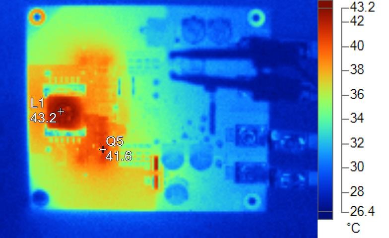
2.4.1.2.5 Thermal Image 12 VIN and 30
AOUT
Name |
Temperature |
L1
|
43.2°C
|
Q5
|
41.6°C
|