TIDT290 August   2022


  1.   Description
  2.   Features
  3.   Applications
  4. 1Test Prerequisites
    1. 1.1 Voltage and Current Requirements
    2. 1.2 Required Equipment
  5. 2Testing and Results
    1. 2.1 Efficiency Graphs
    2. 2.2 Efficiency Data
    3. 2.3 Thermal Images
    4. 2.4 Bode Plots
  6. 3Waveforms
    1. 3.1 Switching
    2. 3.2 Output Voltage Ripple
    3. 3.3 Load Transients
    4. 3.4 Start-Up Sequence
    5. 3.5 Shutdown Sequence
    6. 3.6 Input Voltage Ripple

Bode Plots

The following image shows the PMP31087 bode plot.
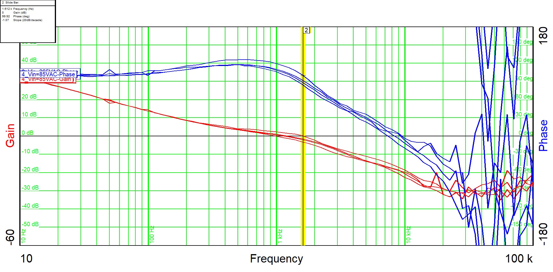
GUID-20220525-SS0I-JT3G-L89D-1VGLCXCVVC1T-low.jpgFigure 2-6 Bode Plot
Input Voltage Output Phase Margin Gain Margin Bandwidth

85 VAC

Full Load

102 deg

> 15 dB

1.2 kHz

110 VAC

Full Load

107 deg

> 15 dB

1.1 kHz

230 VAC

Full Load

106 deg

> 15 dB

0.99 kHz