TIDT322 august 2023
3.4 Load Transients
Load transient response is shown in the following figures.
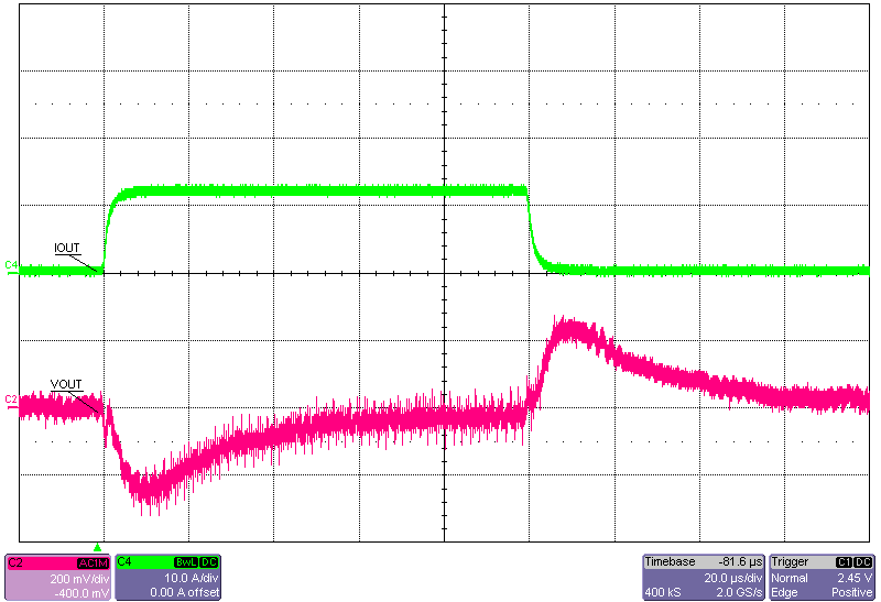
 Figure 3-19 12-V Input, 0-A to12-A Load Step, FPWM
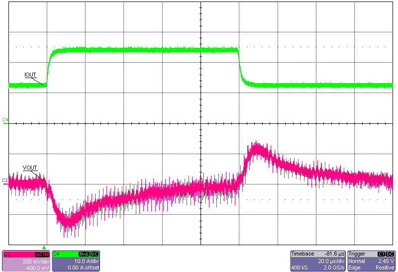
 Figure 3-21 8-V Input, 12-A to 24-A Load Step
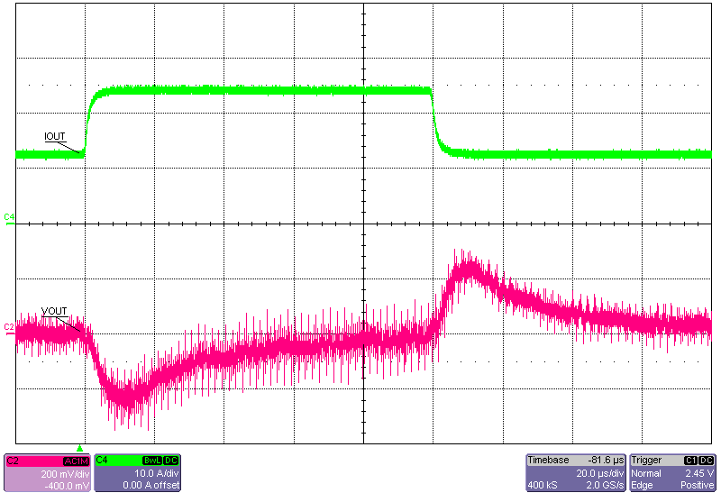
 Figure 3-20 12-V Input, 12-A to 24-A Load Step
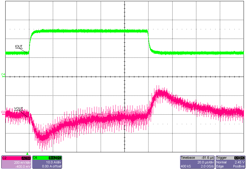
 Figure 3-22 16-V Input, 12-A to 24-A Load Step