TIDT331 august 2023
2.3 Thermal Images
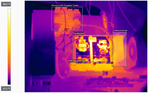
The parameters of Table 2-2 and Figure 2-2 are taken under the following conditions:
- Input: 385 VDC
- Output: 54-V, 56-A load
- Switching frequency: 140 kHz
- Primary GaN turn-on slew rate: 20 V/ns
- Dead-time: 80 ns at 3-kW load
- PFB0412EN-E fan used to provide forced air across PSFB power stage
Table 2-2 summarizes the peak temperature of the major components within the PSFB power stage
Table 2-2 Power Stage Component
Temperatures
| Component | Temperature (°C) |
|---|---|
| Primary GaN daughter cards | 38.5 |
| Transformer | 65.2 |
| SR daughter card | 48.8 |
| Output inductor | 46.8 |
 Figure 2-2 3-kW Thermal Image