TIDT331 august 2023
3.1 Start-Up
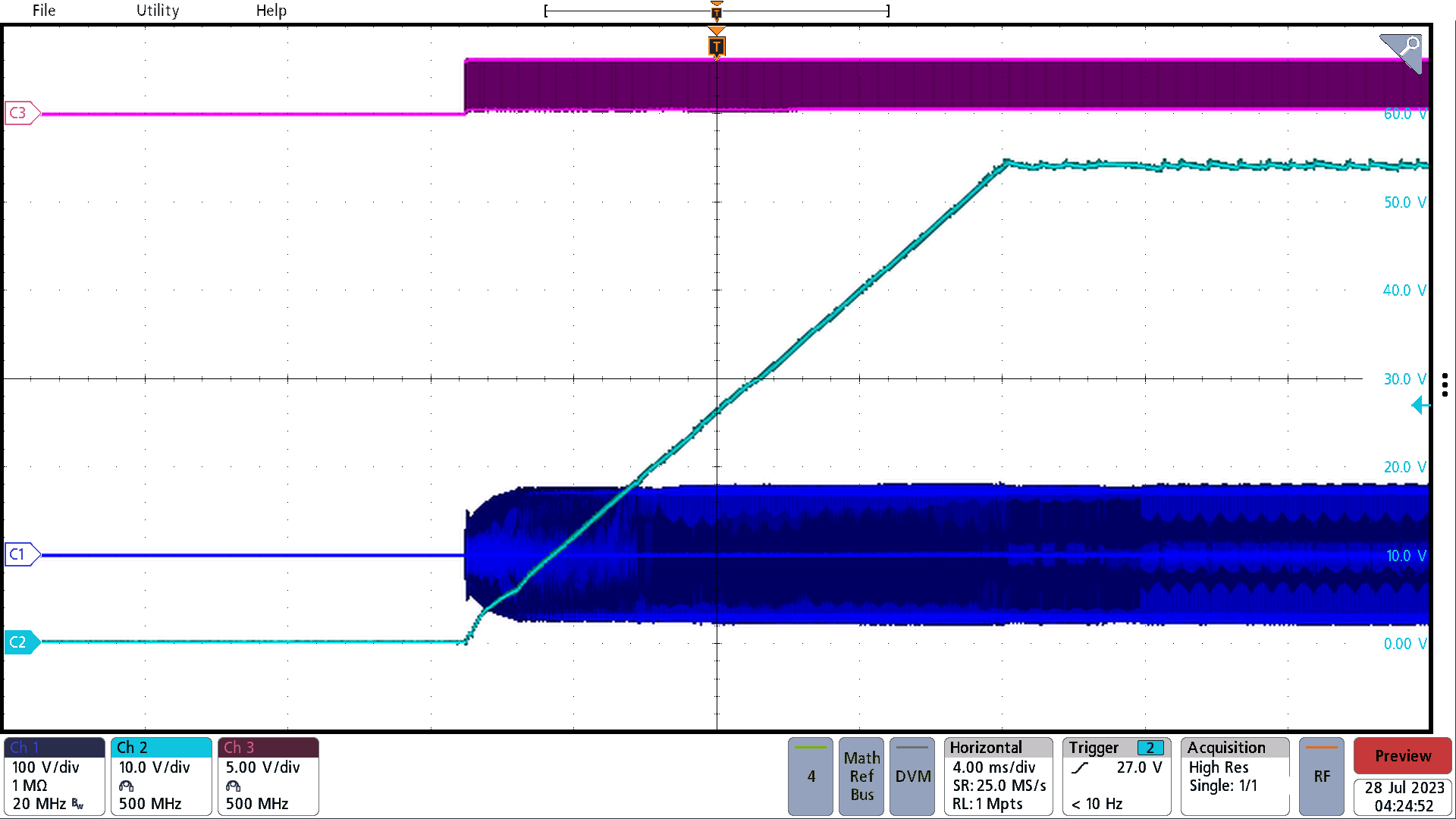
Figure 3-3 illustrates the start-up behavior of the PMP22951 with a 2-A load.
C1 = Secondary Winding Voltage, C2 = Output Voltage, C3 = Leg1 Low-Side PWM
 Figure 3-1 385-V Input, 54-V Output Start-Up
TIDT331 august 2023
Figure 3-3 illustrates the start-up behavior of the PMP22951 with a 2-A load.
C1 = Secondary Winding Voltage, C2 = Output Voltage, C3 = Leg1 Low-Side PWM
 Figure 3-1 385-V Input, 54-V Output Start-Up