TIDT354 November 2023
2.3 Thermal Images
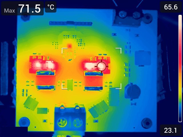
The thermal image presented in Figure 3-11 was taken with a load of 60 A, 24 VIN, and with a fan blowing on the device. Both low-side FETs reached a temperature of 72°C, with the ambient room temperature at 21°C to 23°C.
 Figure 2-3 24-VIN Thermal
Image
Figure 2-3 24-VIN Thermal
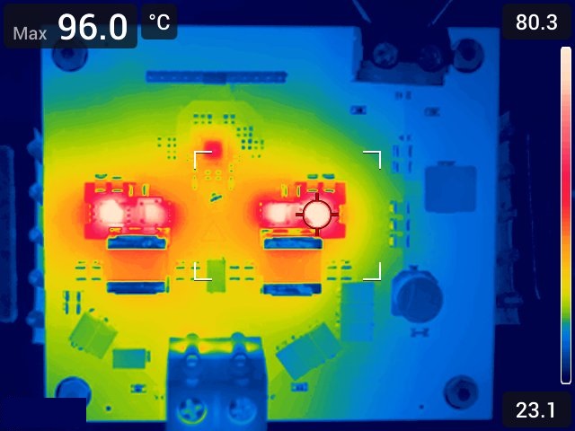
ImageThe thermal image displayed in Figure 2-4 was taken with a load of 60 A, 48 VIN, and with a fan. Both low-side FETs reached a temperature of 96°C, with the ambient room temperature at 21°C to 23°C.
 Figure 2-4 48-VIN Thermal
Image