TIDT360 November   2023


  1.   1
  2.   Description
  3.   Features
  4.   Applications
  5. 1Test Prerequisites
    1. 1.1 Voltage and Current Requirements
    2. 1.2 Required Equipment
    3. 1.3 Considerations
    4. 1.4 Dimensions
  6. 2Testing and Results
    1. 2.1 Efficiency Graphs
    2. 2.2 Efficiency Data
    3. 2.3 Thermal Images
    4. 2.4 Bode Plots
  7. 3Waveforms
    1. 3.1 Switching
    2. 3.2 Output Voltage Ripple
    3. 3.3 Load Transients

Bode Plots

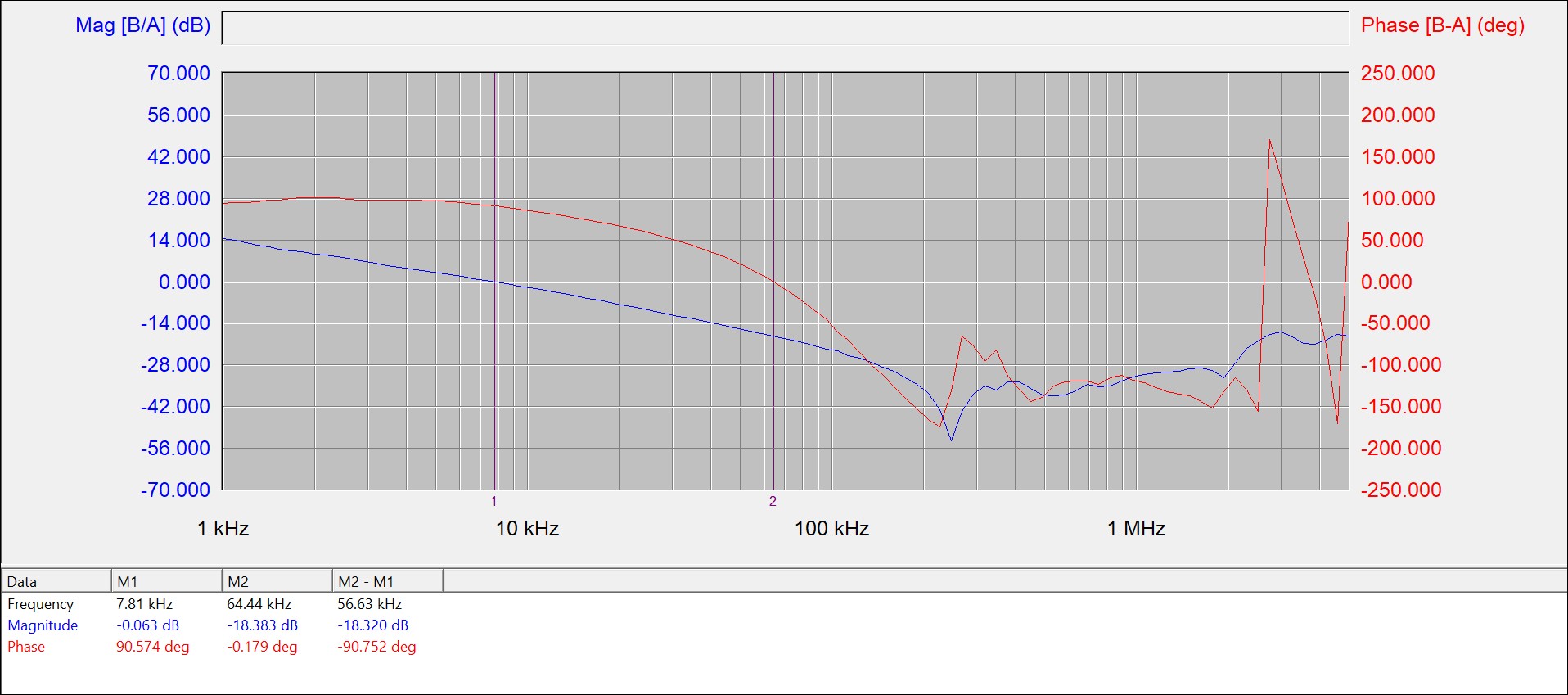
The bode plot is shown in the following figure.
GUID-20231030-SS0I-JBBH-B1F1-PVF53WWDBVSX-low.jpg
Gain Margin (GM) = 18.32 dB; Phase Margin (PM) = 90.75̊ ; Crossover Frequency (fc) = 7.81 kHz
Figure 2-3 Bode Plot of the Main Boost Stage at Full Load, Iload = 10 A, VIN = 12 V, VOUT = 45 V