TIDT388 February 2024
3.1 Switching
Figure 3-43 through Figure 3-9 show the switch node voltages of the buck converter at various operating conditions.
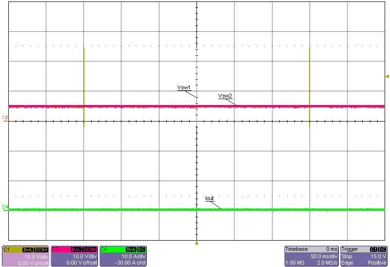 Figure 3-1 Switch Node Voltages, 24V Input, No
Load, PFM Mode
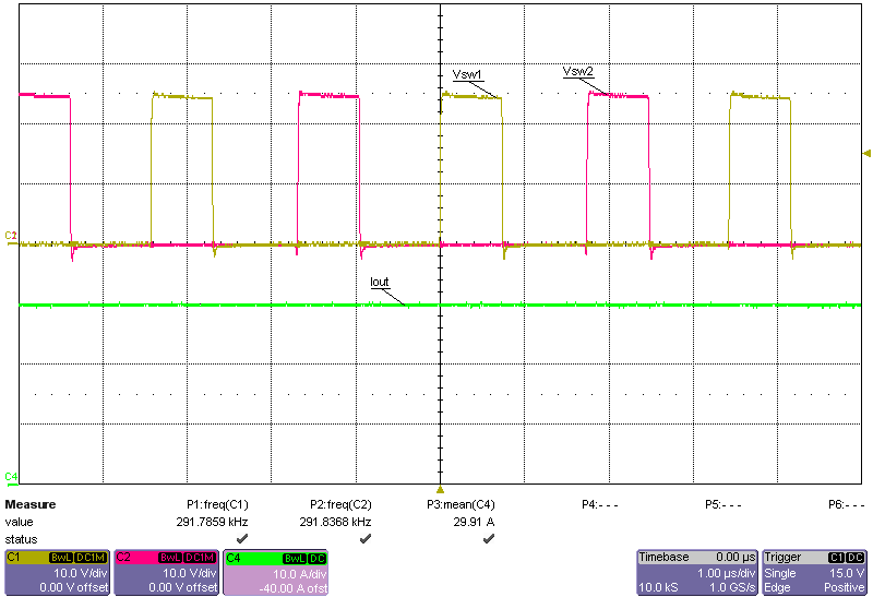 Figure 3-3 Switch Node Voltages, 24V Input, 30A Load
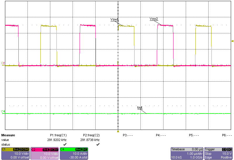 Figure 3-2 Switch Node Voltages, 24V Input, No
Load, FPWM Mode
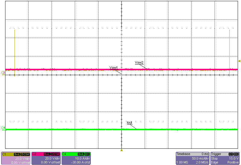 Figure 3-4 Switch Node Voltages, 48V Input, No
Load, PFM Mode
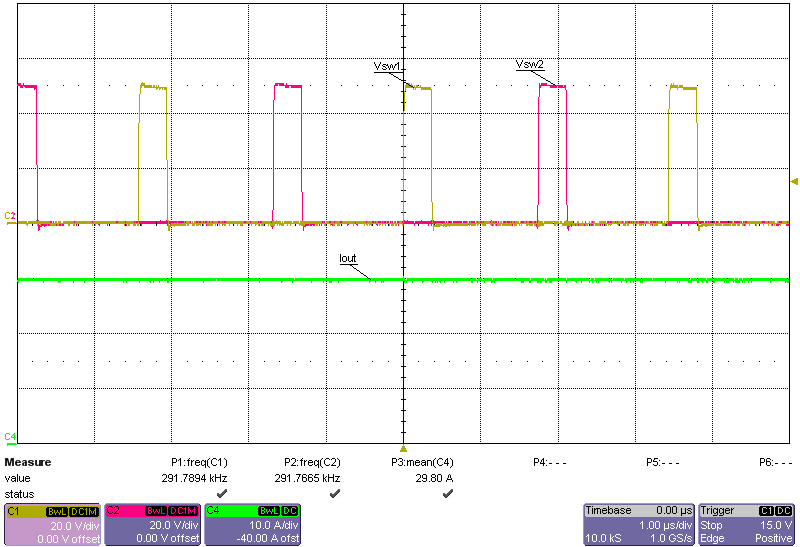 Figure 3-6 Switch Node Voltages, 48V Input, 30A
Load
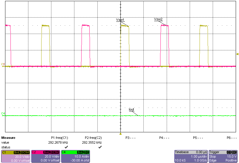 Figure 3-5 Switch Node Voltages, 48V Input, No
Load, FPWM Mode
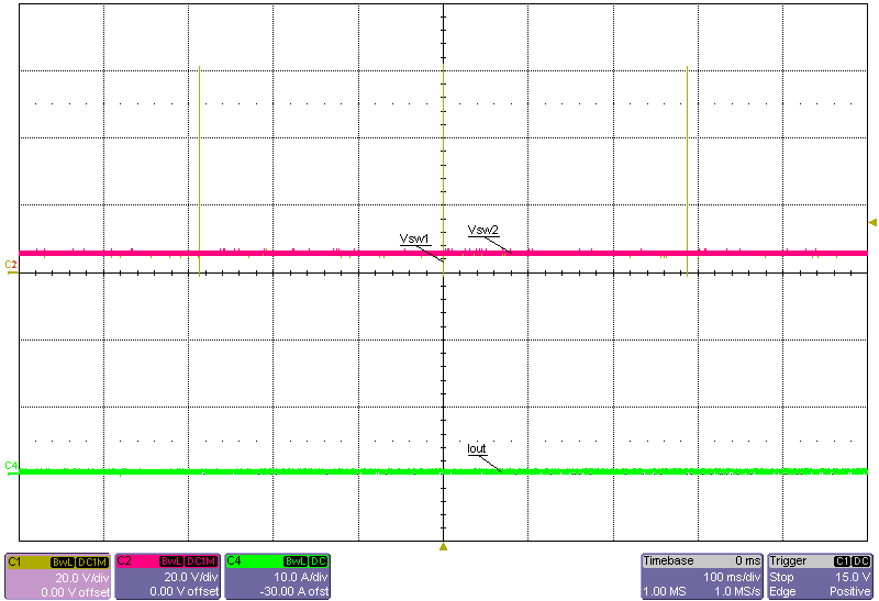 Figure 3-7 Switch Node Voltages, 60V Input, No
Load, PFM Mode
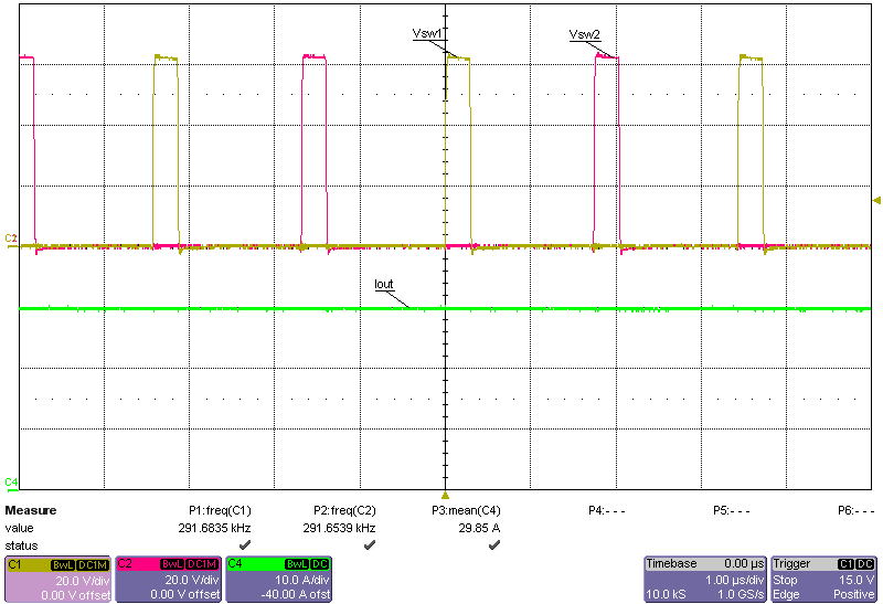 Figure 3-9 Switch Node Voltages, 60V Input, 30A
Load
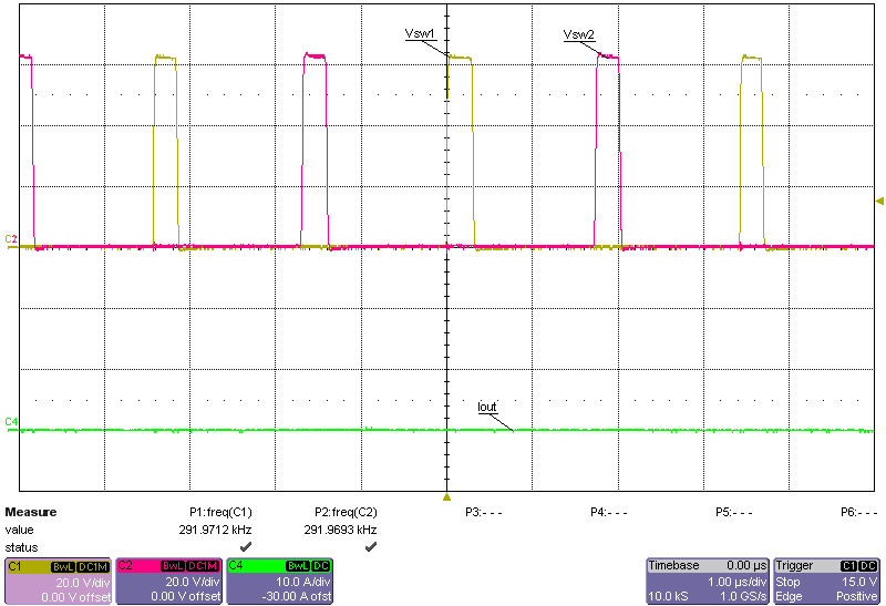 Figure 3-8 Switch Node Voltages, 60V Input, No
Load, FPWM Mode