TIDT394 May 2024
2.4 Bode Plots
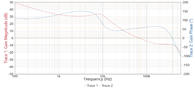
Figure 2-5 illustrates the PMP23389 bode plot.
 Figure 2-5 12V Input, 5.1V, 15A Output; Bandwidth =
68kHz, Phase Margin = 56.5 Degrees,
Figure 2-5 12V Input, 5.1V, 15A Output; Bandwidth =
68kHz, Phase Margin = 56.5 Degrees,Gain Margin = 9.2dB
TIDT394 May 2024
Figure 2-5 illustrates the PMP23389 bode plot.
 Figure 2-5 12V Input, 5.1V, 15A Output; Bandwidth =
68kHz, Phase Margin = 56.5 Degrees,