TIDT397 October 2024
2.1.2 Steady State Waveforms
Steady state switching waveforms are shown in Figure 2-3 through Figure 2-7.
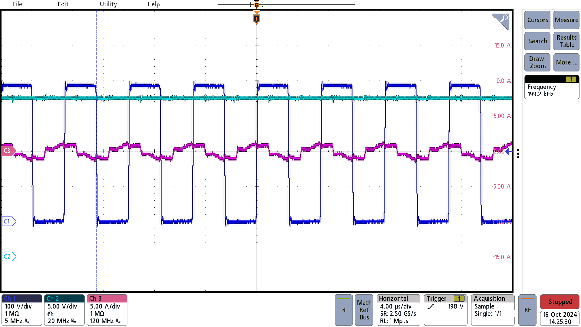
C1 = switch node, C2 =
Vout, C3 = resonant current
Figure 2-3 385Vin, No
Load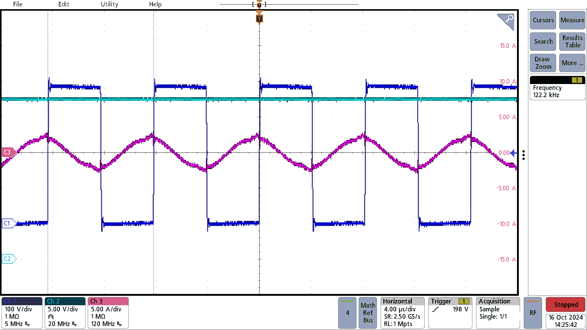
C1 =switch node, C2 =
Vout, C3 = resonant current
Figure 2-4 385Vin, 3A
Load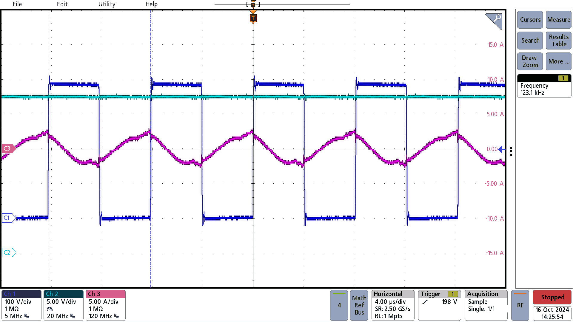
C1 = switch node, C2 =
Vout, C3 = resonant current
Figure 2-5 385Vin, 6A
Load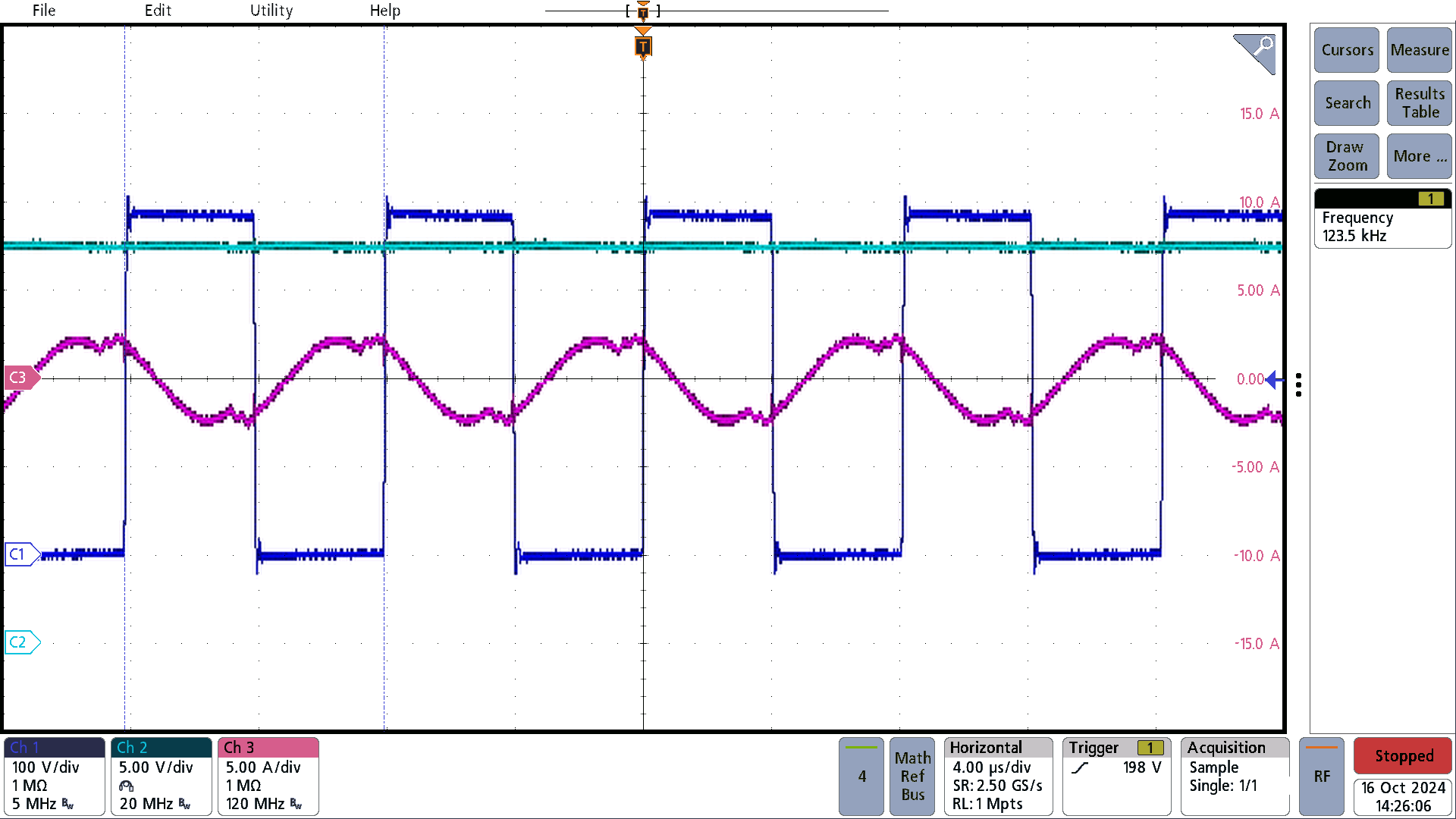
C1 =switch node, C2 =
Vout, C3 = resonant current
Figure 2-6 385Vin, 9A
Load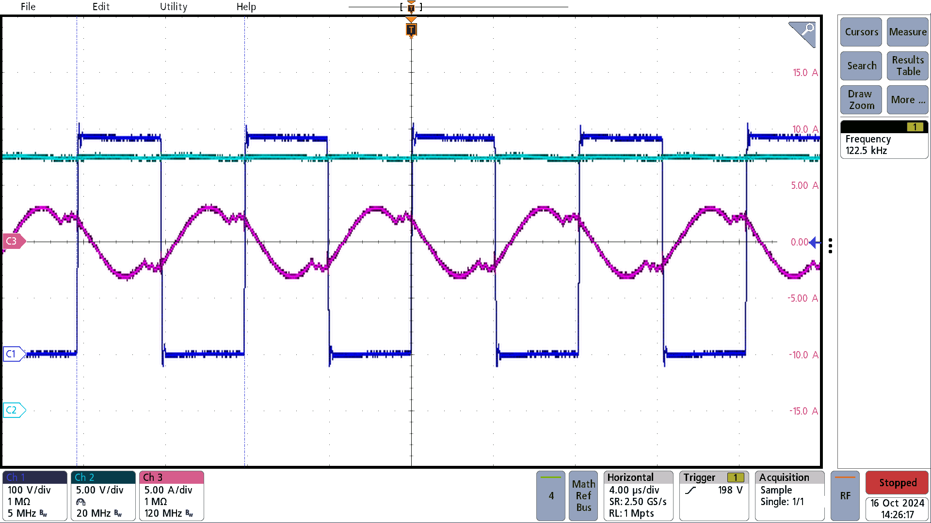
C1 = switch node, C2 =
Vout, C3 = resonant current
Figure 2-7 385Vin, 13.5A
Load