TIDT423 December 2024
2.4 Thermal Images
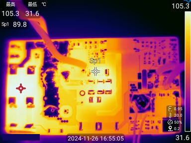
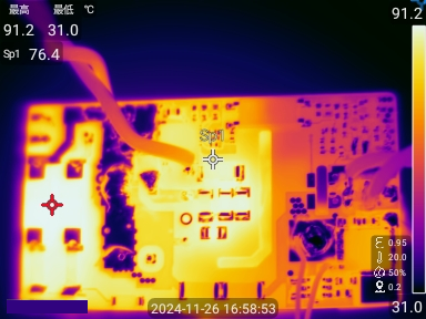
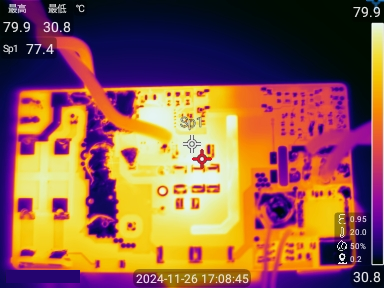
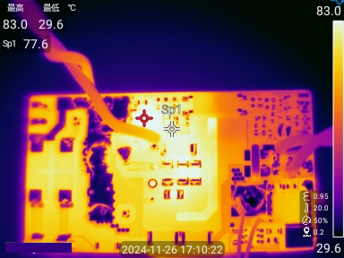
Thermal image is shown in Figure 2-5 through Figure 2-3.
Table 2-2 Thermal Test
Result
| Parts | 90VAC | 115VAC | 230VAC | 264VAC | |
|---|---|---|---|---|---|
| Temperature(oC) | Temperature(oC) | Temperature(oC) | Temperature(oC) | Room temperature(oC) | |
| AC Bridge | 105 | 90 | 75 | 73 | 25 |
| UCG28826 | 84 | 76 | 79 | 83 | 25 |
| Transformer | 75 | 75 | 76 | 77 | 25 |
| SR MOSFET | 68 | 66 | 67 | 66 | 25 |
| RCD Snubber | 91 | 83 | 80 | 79 | 25 |
 Figure 2-5 Thermal, 90VAC, Full Load
 Figure 2-6 Thermal, 115VAC, Full Load
 Figure 2-7 Thermal, 230VAC, Full Load
 Figure 2-8 Thermal, 264VAC, Full Load