TIDT427
December
2024
-
1
-
Description
-
Features
-
Applications
-
1Test Prerequisites
- 1.1
Voltage and Current Requirements
- 1.2
Dimensions
- 1.3
Considerations
-
2Testing and Results
- 2.1
Efficiency Graph
- 2.2
Efficiency Data
- 2.2.1
30V Input Voltage
- 2.2.2
48V Input Voltage
- 2.2.3
60V Input Voltage
- 2.3
Thermal Images
- 2.3.1
Thermal Images at 48VIN,
12VOUT, 10A, No Heatsink
- 2.3.2
Thermal Images at 48VIN,
12VOUT, 20A, RS-PRO 750-0951 Heatsink
- 2.4
Bode Plots
- 2.4.1
30V Input Voltage
- 2.4.2
48V Input Voltage
- 2.4.3
60V Input Voltage
-
3Waveforms
- 3.1
Switching
- 3.1.1
48V Input Voltage
- 3.1.1.1
0A Output Current
- 3.1.1.2
20A Output Current
- 3.1.2
60V Input Voltage
- 3.1.3
30V Input Voltage
- 3.2
Output Voltage Ripple
- 3.3
Input Voltage Ripple
- 3.4
Load Transients
2.3.2 Thermal Images at 48VIN,
12VOUT, 20A, RS-PRO 750-0951 Heatsink
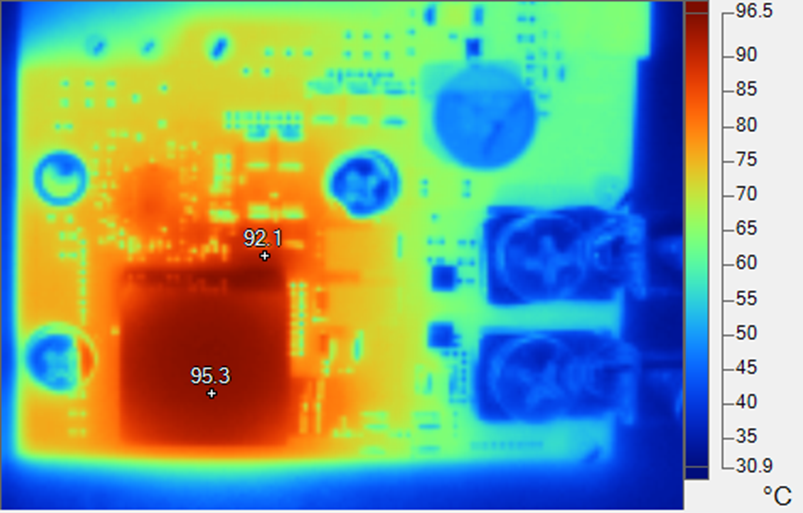
 Figure 2-4 Top Side: Inductor (95°C), GaN IC
Thermal Pad Vias (92°C)
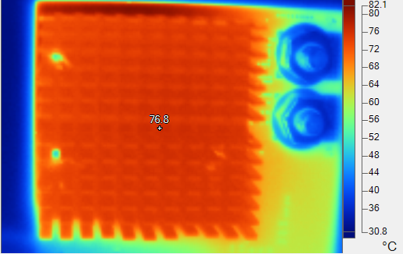
 Figure 2-5 Bottom Side: Heatsink (76°C)
 Figure 2-4 Top Side: Inductor (95°C), GaN IC
Thermal Pad Vias (92°C)
 Figure 2-5 Bottom Side: Heatsink (76°C)
 Figure 2-4 Top Side: Inductor (95°C), GaN IC
Thermal Pad Vias (92°C)
 Figure 2-5 Bottom Side: Heatsink (76°C)