TIDU312A
May 2014 – November 2020
Trademarks
1
Introduction
1.1
PFC Stage Implementation
1.2
BL PFC Electrical Specifications
2
Software Overview
2.1
Software Control Flow
2.2
Incremental Builds
3
Procedure for Running the Incremental Builds
3.1
Build 1: Open-Loop Boost With ADC Measurements
3.1.1
Build 1 Objective
3.1.2
Build 1 Overview
3.1.3
Build 1 Protection
3.1.4
Build 1 Procedure
3.1.4.1
Step 1.1: Start CCS and Open a Project
3.1.4.2
Step 1.2: Device Initialization, Main, and ISR Files
3.1.4.3
Step 1.3: Build and Load the Project
3.1.4.4
Step 1.4: Debug the Environment Windows
3.1.4.4.1
Step 1.5: Use Real-Time Emulation
3.1.4.4.2
Step 1.6: Run the Code for Build 1
3.2
Build 2: BL PFC With Closed-Current Loop
3.2.1
Build 2 Objective
3.2.2
Build 2 Overview
3.2.3
Build 2 Procedure
3.2.3.1
Step 2.1: Build and Load Project
3.3
Build 3: BL PFC With Closed Voltage and Current Loop
3.3.1
Build 3 Objective
3.3.2
Build 3 Overview
3.3.3
Build 3 Procedure
3.3.3.1
Step 3.1: Build and Load Project
4
Test Results
5
References
6
Revision History
4
Test Results
Ch2 – Vin
Ch4 – lin
Vrms = 220V
Vbus = 400V
Figure 4-1
BL PFC Input Voltage and Current Waveforms (Pout = 300W)
Ch2 – Vin
Ch4 – lin
Vrms = 220V
Vbus = 400V
Figure 4-2
BL PFC Input Voltage and Current Waveforms (Pout = 150W)
Ch2 – Vin
Ch4 – lin
Vrms = 220V
Vbus = 400V
Figure 4-3
BL PFC Input Voltage and Current Waveforms (Pout = 60W)
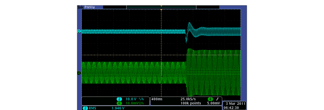
Ch2 – Vbus
Ch4 – lin
Vbus = 400V
Load Step 150W ~ 300W
Figure 4-4
BL PFC DC Bus Load Transient Response (Vrms = 110V)
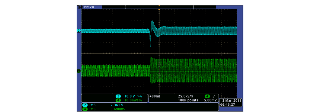
Ch2 – Vbus
Ch4 – lin
Vbus = 400V
Load Step 150W ~ 300W
Figure 4-5
BL PFC DC Bus Load Transient Response (Vrms = 220V)