TIDU312A May   2014  – November 2020


  1.   Trademarks
  2. 1Introduction
    1. 1.1 PFC Stage Implementation
    2. 1.2 BL PFC Electrical Specifications
  3. 2Software Overview
    1. 2.1 Software Control Flow
    2. 2.2 Incremental Builds
  4. 3Procedure for Running the Incremental Builds
    1. 3.1 Build 1: Open-Loop Boost With ADC Measurements
      1. 3.1.1 Build 1 Objective
      2. 3.1.2 Build 1 Overview
      3. 3.1.3 Build 1 Protection
      4. 3.1.4 Build 1 Procedure
        1. 3.1.4.1 Step 1.1: Start CCS and Open a Project
        2. 3.1.4.2 Step 1.2: Device Initialization, Main, and ISR Files
        3. 3.1.4.3 Step 1.3: Build and Load the Project
        4. 3.1.4.4 Step 1.4: Debug the Environment Windows
          1. 3.1.4.4.1 Step 1.5: Use Real-Time Emulation
          2. 3.1.4.4.2 Step 1.6: Run the Code for Build 1
    2. 3.2 Build 2: BL PFC With Closed-Current Loop
      1. 3.2.1 Build 2 Objective
      2. 3.2.2 Build 2 Overview
      3. 3.2.3 Build 2 Procedure
        1. 3.2.3.1 Step 2.1: Build and Load Project
    3. 3.3 Build 3: BL PFC With Closed Voltage and Current Loop
      1. 3.3.1 Build 3 Objective
      2. 3.3.2 Build 3 Overview
      3. 3.3.3 Build 3 Procedure
        1. 3.3.3.1 Step 3.1: Build and Load Project
  5. 4Test Results
  6. 5References
  7. 6Revision History

Test Results

GUID-644BB744-849E-4222-9930-A45AA8DC7EF0-low.gif
Ch2 – Vin
Ch4 – lin
Vrms = 220V
Vbus = 400V
Figure 4-1 BL PFC Input Voltage and Current Waveforms (Pout = 300W)
GUID-23AEBA82-BD67-4DAD-AAB5-2A918352363D-low.gif
Ch2 – Vin
Ch4 – lin
Vrms = 220V
Vbus = 400V
Figure 4-2 BL PFC Input Voltage and Current Waveforms (Pout = 150W)
GUID-B95AEDBC-0221-41F9-B1B1-7D7017D6133F-low.gif
Ch2 – Vin
Ch4 – lin
Vrms = 220V
Vbus = 400V
Figure 4-3 BL PFC Input Voltage and Current Waveforms (Pout = 60W)
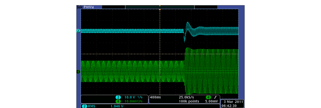
GUID-0C97FECA-F8D2-406E-A067-9A297EB0C4DD-low.gif
Ch2 – Vbus
Ch4 – lin
Vbus = 400V
Load Step 150W ~ 300W
Figure 4-4 BL PFC DC Bus Load Transient Response (Vrms = 110V)
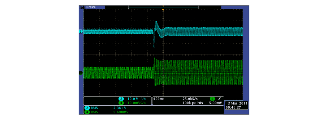
GUID-B37030FA-469E-4D71-8828-6D527BD29BCA-low.gif
Ch2 – Vbus
Ch4 – lin
Vbus = 400V
Load Step 150W ~ 300W
Figure 4-5 BL PFC DC Bus Load Transient Response (Vrms = 220V)