TIDUAH1A August 2015 – April 2018
3.1.1.1 Connectors
Table 10. Connector Details
| INPUT/OUTPUT TYPE | SPECIFICATION | CONNECTOR |
|---|---|---|
| INPUTS | ||
| Voltage I/P | Channel 1 | J11 |
| Channel 2 | J12 | |
| Channel 3 | J13 | |
| OUTPUTS | ||
| Analog Output | Analog Output 0 (AOUT0) | J9.3 – J9.4 |
| Analog Output 1 (AOUT1) | J9.1 – J9.2 | |
| Analog output parameter selection(1)
(connect jumper between mentioned pins) |
Phase 1 (AOUT0 = V1; AOUT1 = I1) | J4.1 – J4.2 |
| Phase 2 (AOUT0 = V2; AOUT1 = I2) | J4.3 – J4.4 | |
| Phase 3 (AOUT0 = V3; AOUT1 = I3) | J4.5 – J4.6 | |
| Analog output type (voltage ±10 V or current ±24 mA) selection
(connect jumper between mentioned pins) |
AOUT0 = ±10-V voltage mode | J3.2 – J3.3 |
| AOUT0 = ±24-mA current mode | J4.7 – J4.8,
J3.2 – J3.3 |
|
| AOUT1 = ±24-mA current mode | J3.2 – J3.3 | |
| AOUT1 = ±10-V voltage mode | J4.9 – J4.10,
J3.2 – J3.3 |
|
| Digital (relay) output (connect 8.5 V or higher on J1.2 to J2.1 for operation of relay driver IC) | Channel 1 | J1.8 – J1.1 |
| Channel 2 | J1.7 – J1.1 | |
| Channel 3 | J1.6 – J1.1 | |
| Channel 4 | J1.5 – J1.1 | |
| Channel 5 | J1.4 – J1.1 | |
| Channel 6 | J1.3 – J1.1 | |
| POWER SUPPLY | ||
| Non-isolated power supply input | 12-V dc | J8.1 wrt J8.2 |
| Isolated power supply input | 15-V dc | J14.1 wrt J14.4 |
| –15-V dc | J14.2 wrt J14.4 | |
| MCU | ||
| MCU programming | JTAG | J10 |
| Expansion I/O interface | SPI, I2C, UART, and GPIO | J5, J2, J4 |
(1) Analog output parameter selection: The appropriate phase jumper must be connected. The analog output is at mid-value and no data sends in the case that no jumper is connected for the phase selection. In the case where multiple jumpers are connected for phase selection, priority is given as per phase 1 > phase 2 > phase 3. For example, if phase 1 and phase 2 jumpers are connected, phase 1 receives priority and phase 1 data sends to the analog outputs.
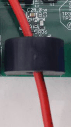
The current input wires are taken through the current transformer and do not have connectors (see Figure 22). The wires are connected externally as flying leads. An external terminal block can be used to connect the current inputs.
 Figure 22. Current Input Wire Through CT
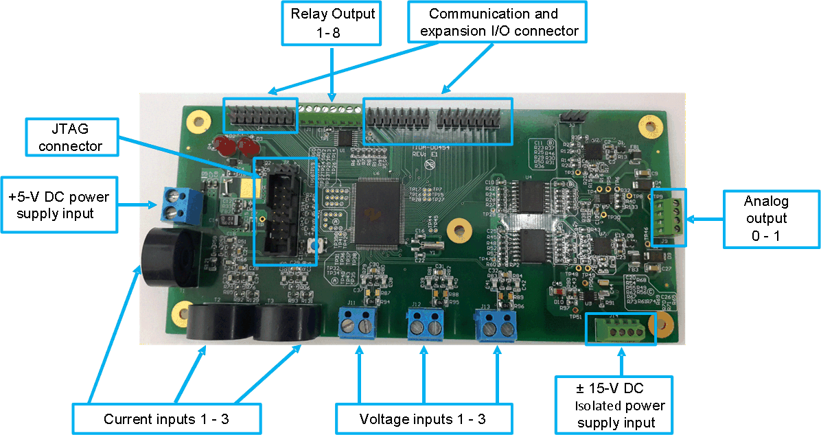
Figure 23 shows the interface connectors for the TIDA-00454 board.
 Figure 23. TIDA-00454 Interface Connectors