TIDUDO6B May 2019 – October 2020
- Description
- Resources
- Features
- Applications
- 5
- 1System Description
-
2System Overview
- 2.1 Block Diagram
- 2.2 Highlighted Products
- 2.3
System Design Theory and Design Considerations
- 2.3.1 AFE4900 and Power Supply
- 2.3.2 CC2640R2F Microcontroller
- 2.3.3 PPG Measurement
- 2.3.4 ECG Measurement
- 2.3.5 Selecting TX Supply (TX_SUP) Value for Driving LEDs
- 2.3.6 Generating TX Supply for Driving LEDs
- 2.3.7 Generating RX Supply for AFE4900
- 2.3.8 Generating I/O Supply
- 2.3.9 Battery Input and Reservoir Capacitors
- 2.3.10 Battery Life Calculations
- 2.3.11 External Memory
- 2.3.12 LED Indications
- 2.3.13 Connections Between Sensor Board and ECG Board
-
3Hardware, Software, Testing Requirements, and Test Results
- 3.1 Required Hardware and Software
- 3.2 Testing and Results
-
4Design Files
- 4.1 Schematics
- 4.2 Bill of Materials
- 4.3
PCB Layout Recommendations
- 4.3.1 Layout for Main Board
- 4.3.2 Connection From PDs to AFE
- 4.3.3 Connections From LEDs to AFE
- 4.3.4 Connections From ECG PADs to AFE
- 4.3.5 Connections Between BT and AFE
- 4.3.6 Connections Between BT Antenna and Chip
- 4.3.7 Boost Converter
- 4.3.8 Buck-Boost Converter
- 4.3.9 Layouts for PPG Sensor Boards
- 4.3.10 Layout for ECG Sensor Board
- 4.3.11 Layout Prints
- 4.4 Altium Project
- 4.5 Gerber Files
- 4.6 Assembly Drawings
- 5Software Files
- 6Related Documentation
- 7About the Authors
- Revision History
3.1.2.2 LabVIEW™ File Execution for Checking Measurement Data (Receive Side of BLE)
Only one device, the LAUNCHXL-CC2640R2 or XDS110, can be connected to the PC while running the executable file.
- Insert one CR3032 battery into the BT1 connector on the TIDA-01580 board and power it on by using the S2 switch (ensure J8 is shorted on the TIDA-01580 board). Ignore this step if it was already done during programming of the TIDA-01580 board.
- Revert back to the original LaunchPAD jumper settings.
- Plug in the LAUNCHXL-CC2640R2 device on the USB port of the PC.
- Open the Setup_TIDA-01580.exe file and go through the installation process, explained as follows.
- Setup Welcome Screen – click Next.
 Figure 3-11 Setup Welcome Screen
 - License Agreement Screen – Accept the agreement and click Next.
 Figure 3-12 License Agreement Screen
 - Installation Directory Screen – click Next.
 Figure 3-13 Installation Directory Screen
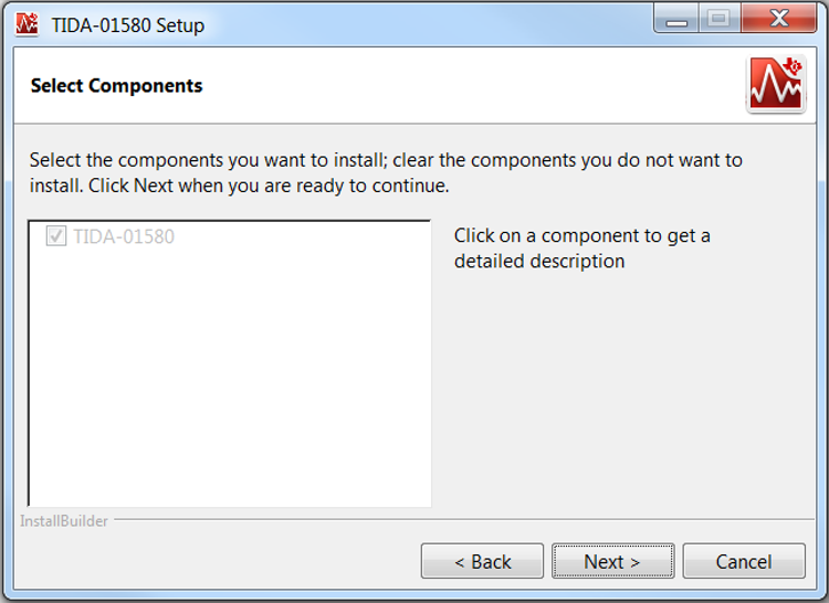
 - Select Components Screen – click Next.
 Figure 3-14 Select Components Screen
 - Ready to Install Screen – click Next.
 Figure 3-15 Ready to Install Screen
The setup starts installing and the progress screen is displayed (see Figure 3-16).
 Figure 3-16 Installing GUI
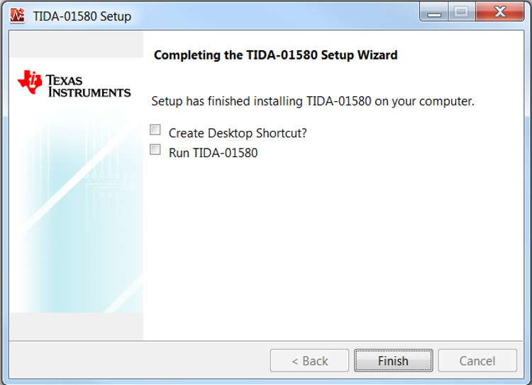
 - When installed, click Finish. Look for the TIDA-01580 Application.exe at the installed location (default location: C:\Program Files (x86)\Texas Instruments\TIDA-01580\TIDA-01580 Application).
 Figure 3-17 Completing TIDA-01580 Setup Wizard
While launching the GUI, a splash screen appears, as shown in Figure 3-18.
 Figure 3-18 Splash Screen on Launching TIDA-01580 GUI
The Instructions tab provides instructions and safety precautions for the user, as shown in Figure 3-19.
 Figure 3-19 TIDA-01580 GUI Instructions Tab
- Setup Welcome Screen – click Next.
The Configurations tab (see Figure 3-20) provides information about the software paths.
- Ensure the CCS base-folder path is set to <CCS installation path>\ccsv7\ccs_base.
- Ensure the project .OUT file path is set to <installation folder>\TIDA-01580_firmware\TIDA-01580_firmware_rx\FlashROM_StackLibrary\TIDA-01580_firmware_rx.out.
- The START/STOP button can connect and program the LAUNCHXL-CC2640R2 device to capture the data. After clicking the START/STOP button, the TIDA-01580 board must immediately be power cycled using the S2 switch. The START/STOP button can also disconnect the link.
 Figure 3-20 TIDA-01580 GUI Configurations Tab
The HRM tab (see Figure 3-21) shows PPG data taken from green LED and ECG data. The HRM tab estimates heart-rate from both sets of data (time difference in seconds between two peaks of PPG or ECG data / 60).
As soon as the BLE connection is established, the Configurations tab switches to the HRM tab.
 Figure 3-21 TIDA-01580 GUI HRM Tab
The SpO2 tab (see Figure 3-22) shows PPG data taken from the red and IR LEDs. The SpO2 tab estimates % SpO2 from both sets of data.
 Figure 3-22 TIDA-01580 GUI SpO2 Tab
- The LED indication of BLE Connected? turns on if the LAUNCHXL-CC2640R2 receiver is connected with the TIDA-01580 board over BLE.
- The LED indication of Low Battery turns on if the battery voltage is less than 2 V.
- The LED indication of Lead Off Detect turns on if any one of the ECG electrodes are not connected to the human body.
- The Exit button can disconnect and quit the .exe file.