TIDUEA0A March 2019 – September 2020
- 1
- Description
- Resources
- Features
- Applications
- 6
- 1System Description
- 2System Overview
-
3Hardware, Software, Testing Requirements, and Test Results
- 3.1 Required Hardware and Software
- 3.2
Testing and Results
- 3.2.1 Test Setup for Performance Testing
- 3.2.2 EMI and EMC Test Requirements for DRTD
- 3.2.3 TMP117 EMI/EMC Test Results
- 3.2.4 TMP117 Based Temperature Probe Measurement Performance Test Results
- 3.2.5 TMP116 Based Temperature Probe Measurement Performance Test Results
- 3.2.6 I2C-bus Cable Length Considerations
- 3.2.7 Power Supply
- 3.2.8 ESD Test Results for TMP116
- 3.2.9 Summary
- 4Design Files
- 5Software Files
- 6Related Documentation
- 7About the Author
- 8Revision History
3.1.2 Interface Test Software for TMP116
Note, the same setup and procedure can be followed to interface to the TMP117 sensor for testing. The TMP116 and TMP117 are also resgister compatible.
The TIDA-010002 has been tested together with the EVM430-FR6047, a reference development platform used to evaluate the performance of the MSP430FR6047 for ultrasonic sensing applications, such as smart water or Heat Meters. The highly-accurate flow measurement of the MSP430FR6047 MCU in combination with the Class AA sensor temperature accuracy delivers a cost-optimized, ultra-low-power hardware platform for designing Heat and Cooling Meters or Heat Calculators.
 Figure 3-1 EVM430-FR6047 With a 6-m DRTD (TIDA-010002 is Sealed Inside the Metal Body)
The MSP430FR6047 application software is called Ultrasonic Sensing (USS) Design Center. To download the software, visit MSP430 MCUs Ultrasonic Sensing Design Center. The MSP-USSSWLIB free software is the basis for the example code provided with the TIDA-010002 design. The MSP-USSSWLIB has three parts, the USSSWLib, the USS Design Center GUI and the Demo Application. As of August, 2018 the latest revision on TI.com is the "UltrasonicWaterFR6047_02_10_00_05_windows_installer.exe" and contains the "MSP430FR6047EVM_USS_Water_Demo" Code Composer Studio project, which is the one used here.
The "hal_system.c" file was modified to enable MSP430FR6047's eUSCI_B0 as the I2C-master for the TIDA-010002 as the slave. The "main.c" file in "Water_Demo" software project has been modified; both read and write access to the TMP116 device is implemented, including the TMP116 EEPROM write function.
The USCI_A1 module of the MSP430FR6047 has been set to operate as the communication interface to the PC (using the back-channel UART of the MSP430 debugger, integrated onto the EVM). The UART settings are 57600,8N1 and the data being output can be monitored inside the Code Composer Studio CCSv8.1.0 by opening a Terminal window; alternatively the user can run his favorite UART terminal program.
The I2C driver for communication with the TMP116 has been developed, utilizing the existing Hardware Abstraction Layer (HAL) driver for the MSP430FR6047 EVM. The I2C-Address of the TIDA-010002 is hard-wired 0x48 hex, with R3 mounted on the TIDA-010002 PCB (see Figure 3-1).
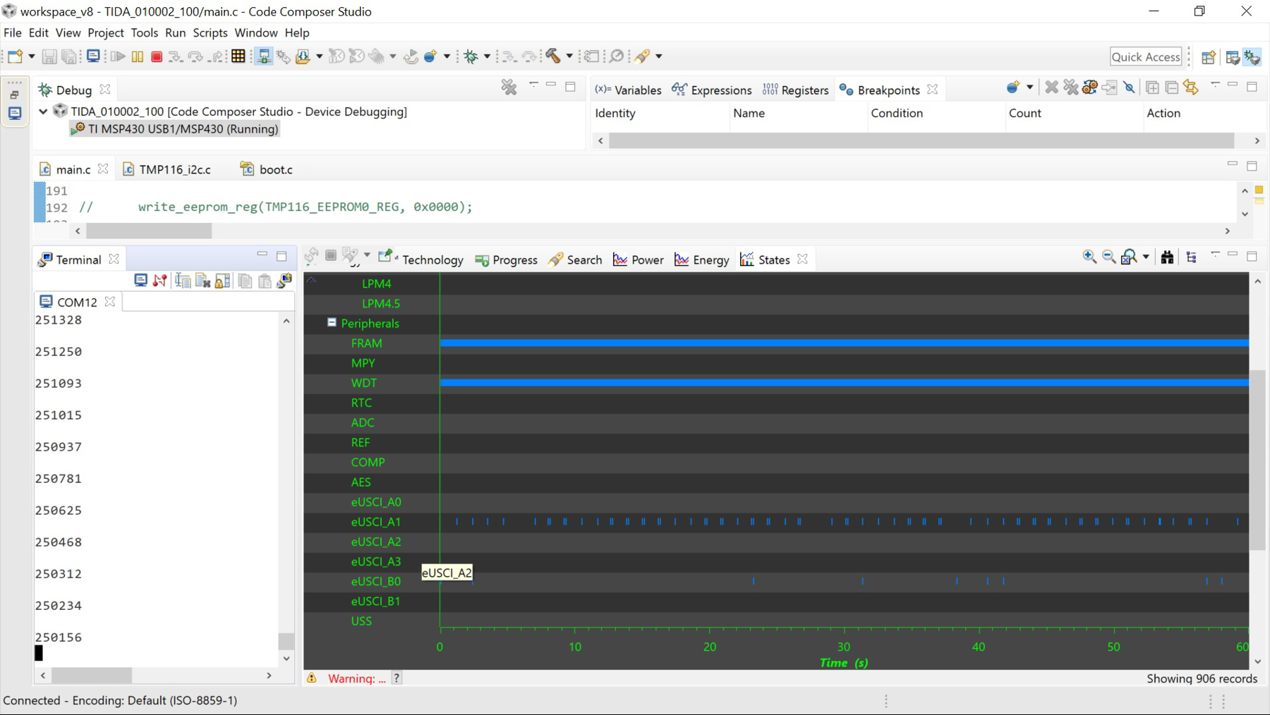
The complete modified Demo Application software is available under BSD Clause 3 license as an open source example in Section 5. When using this code project under CCSv8.3 or later the actual temperature reading is printed into the Terminal window, which is displayed in the bottom left in Figure 3-2. The number format in the terminal is two digits before and 4 digits after the decimal point. Thus the string "251328", which is the first data in the COM12 Terminal window, means +25.1328°C.
Note that below 0°C temperature conversion has not been implemented in the text code and must be added by the user.
The code example uses 8 samples averaging with a cycle of 1 second as the default settings for TMP116 to demonstrate the operation of the complete system. The user should adjust the TMP116 settings as appropriate for his specific application.
 Figure 3-2 TIDA-010002 Code Example With Terminal Output in COM12 and EnergyTrace++
The EnergyTrace++Figure 3-2 window on the bottom right shows the activity of the MSP430 peripherals - see vertical blue stripes in the lines eUSCI_A1 and eUSCI_B0.