TIDUEA0A March 2019 – September 2020
- 1
- Description
- Resources
- Features
- Applications
- 6
- 1System Description
- 2System Overview
-
3Hardware, Software, Testing Requirements, and Test Results
- 3.1 Required Hardware and Software
- 3.2
Testing and Results
- 3.2.1 Test Setup for Performance Testing
- 3.2.2 EMI and EMC Test Requirements for DRTD
- 3.2.3 TMP117 EMI/EMC Test Results
- 3.2.4 TMP117 Based Temperature Probe Measurement Performance Test Results
- 3.2.5 TMP116 Based Temperature Probe Measurement Performance Test Results
- 3.2.6 I2C-bus Cable Length Considerations
- 3.2.7 Power Supply
- 3.2.8 ESD Test Results for TMP116
- 3.2.9 Summary
- 4Design Files
- 5Software Files
- 6Related Documentation
- 7About the Author
- 8Revision History
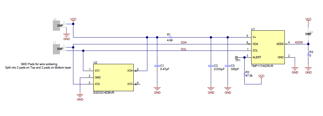
2.4.2 TMP117 Configuration as Temperature Sensor
This section provides details of the digital sensor configuration using TMP117. The key functional blocks include:
TMP117 digital temperature sensor
ESDS314 ESD protection diode
Passive power supply filter for reducing EMI
 Figure 2-6 TMP117-Based Digital Temperature Sensor Circuit Configuration.