TIDUEX1A December   2020  – March 2021


  1.   Description
  2.   Resources
  3.   Features
  4.   Applications
  5.   5
  6. 1System Description
    1. 1.1 Key System Specifications
  7. 2System Overview
    1. 2.1 Block Diagram
    2. 2.2 Design Considerations
    3. 2.3 Highlighted Products
      1. 2.3.1 TMP117 – High-accuracy, low-power, digital temperature sensor
      2. 2.3.2 System Design Theory
        1. 2.3.2.1 System Accuracy
  8. 3Hardware, Software, Testing Requirements, and Test Results
    1. 3.1 Hardware
    2. 3.2 Software
      1. 3.2.1 SysConfig
      2. 3.2.2 Graphical User Interface (GUI)
        1. 3.2.2.1 Launching and Running the Software
        2. 3.2.2.2 Using the GUI
          1. 3.2.2.2.1 Home Tab
          2. 3.2.2.2.2 Data Capture Tab
          3. 3.2.2.2.3 EVM Setup Tab
          4. 3.2.2.2.4 Configuration Tab
          5. 3.2.2.2.5 Register Tab
          6. 3.2.2.2.6 Collateral Tab
    3. 3.3 Testing and Results
      1. 3.3.1 Test Setup
        1. 3.3.1.1 System Accuracy
      2. 3.3.2 Test Results
  9. 4Design and Documentation Support
    1. 4.1 Design Files
      1. 4.1.1 Schematics
      2. 4.1.2 BOM
    2. 4.2 Tools and Software
      1. 4.2.1 PCB Layout Recommendations
      2. 4.2.2 Software Files
    3. 4.3 Documentation Support
    4. 4.4 Support Resources
    5. 4.5 Trademarks
  10. 5Revision History
Home Tab

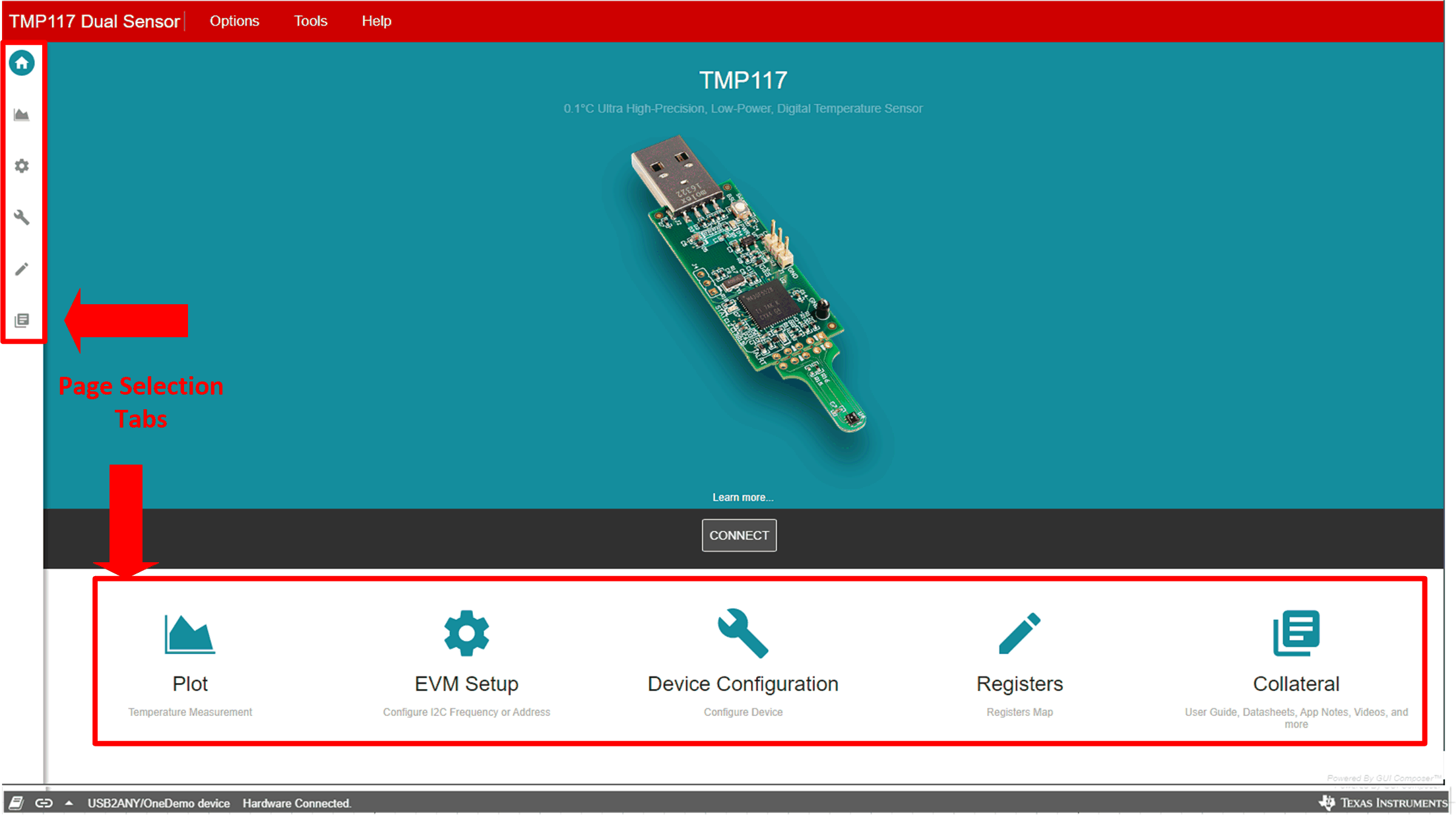
When the TMP117DualSensor_GUI is launched, the Home page will be appeared as shown in Figure 3-9. There are two ways to navigate between tabs. On the bottom half of the Home page contains icons where it links to the five other GUI pages. The icons are identical features to those locked in the left-most border of the TMP117DualSensor_GUI. If TMP117EVM is powered and connected to the PC that has the correct firmware loaded, the Hardware Connected will appear at the left corner of the status bar as well as the connected icon shows solid.
GUID-20200811-CA0I-FKZ4-ZWRX-3665HQGTJMCK-low.gifFigure 3-9 Home Tab