TIDUEX1A December 2020 – March 2021
3.2.2.1 Launching and Running the Software
First, connect the TMP117EVM to a USB port on a PC. The TMP117EVM is recognized by the host as a generic human interface device (HID), so there is no proprietary driver required to install on your PC. It shows the typical response to connecting the USB-to-I2C converter board to a PC USB port for the first time as shown in Figure 3-4. Typically, the computer responds with a Found New Hardware, USB device pop-up dialog. The pop-up window then typically changes to Found New Hardware, USB Human Interface Device. This pop-up window indicates that the device is ready to be used. The USB-to-I2C Converter uses the human interface device drivers that are part of the Microsoft Windows® operating system.
 Figure 3-4 USB Ready
Next, connect directly to the gallery by clicking this link. It requires log on user account privileges to use the online version, as well as, installation of the applications.
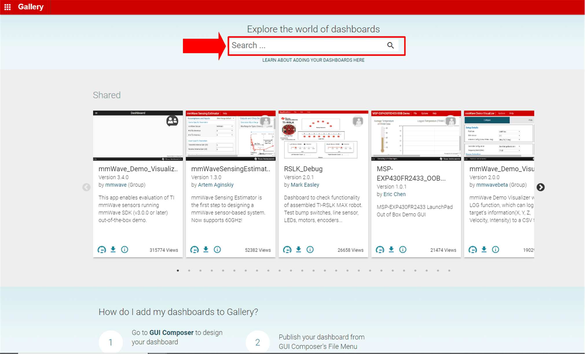
On the top middle of the gallery main page, navigating to the Search field, enter TMP117DualSensor_GUI shown in Figure 3-5.
 Figure 3-5 Gallery Home
Page
Figure 3-5 Gallery Home
PageClick the TMP117DualSensor_GUI icon. Users may be prompted to download and install the browser extension for the Firefox or Chrome and TI Cloud Agent Application for the first time. Click Agree and Proceed.
Follow the steps to install the browser extension and TI Cloud Agent Applications in Figure 3-6.
 Figure 3-6 TI
Cloud Agent Pop up
Figure 3-6 TI
Cloud Agent Pop upAfter installing TI Cloud Agent Applications The TMP117DualSensor_GUI should automatically initialize and connect to the HID port.
A successful connection will show HARDWARE CONNECTED on the bottom of the GUI status indicator as shown in Figure 3-7. If there is a connection problem, verify if the TMP117EVM has an established connection with the PC. A failed connection will shows as HARDWARE NOT CONNECTED shown in Figure 3-8.
 Figure 3-7 Hardware Connected
 Figure 3-8 Hardware Not Connected