TIDUF77 June 2024 MSPM0G1507
- 1
- Description
- Resources
- Features
- Applications
- 6
- 1System Description
-
2System Overview
- 2.1 Block Diagram
- 2.2 Design Considerations
- 2.3 Highlighted Products
- 2.4
System Design Theory
- 2.4.1
Hardware Design
- 2.4.1.1 Modular Design
- 2.4.1.2 Auxiliary Flyback Power Supply
- 2.4.1.3 DC Link Voltage Sensing
- 2.4.1.4 Inrush Current Protection
- 2.4.1.5 Motor Phase Voltage Sensing
- 2.4.1.6 Motor Phase Current Sensing
- 2.4.1.7 Over Current Protection of DRV7308
- 2.4.1.8 Internal Overcurrent Protection for TMS320F2800F137
- 2.4.2 Three-Phase PMSM Drive
- 2.4.1
Hardware Design
-
3Hardware, Software, Testing Requirements, and Test Results
- 3.1 Getting Started Hardware
- 3.2 Getting Started GUI
- 3.3
Getting Started C2000 Firmware
- 3.3.1 Download and Install Software Required for Board Test
- 3.3.2 Opening Project Inside CCS
- 3.3.3 Project Structure
- 3.3.4 Test Procedure
- 3.4
Test Results
- 3.4.1 Fast and clean Rising/Falling Edge
- 3.4.2 Inrush Current Protection
- 3.4.3 Thermal performance under 300VDC
- 3.4.4 Thermal performance under 220VAC
- 3.4.5 Overcurrent Protection by Internal CMPSS
- 3.4.6 IPM Efficiency with External Bias Supply under 300VDC
- 3.4.7 Board Efficiency with Onboard Bias Supply under 300VDC
- 3.4.8 Board Efficiency with External Bias Supply under 220VAC
- 3.4.9 Board Efficiency with Onboard Bias Supply under 220VAC
- 3.4.10 iTHD Test of Motor Phase Current
- 3.4.11 Standby Power Test
- 3.5 Migrate Firmware to a New Hardware Board
- 3.6 Getting Started MSPM0 Firmware
- 4Design and Documentation Support
- 5About the Author
3.1.1 Hardware Board Overview
Figure 3-1 shows an overview of a typical motor inverter system.
 Figure 3-1 Hardware Board Block Diagram of TIDA-010273
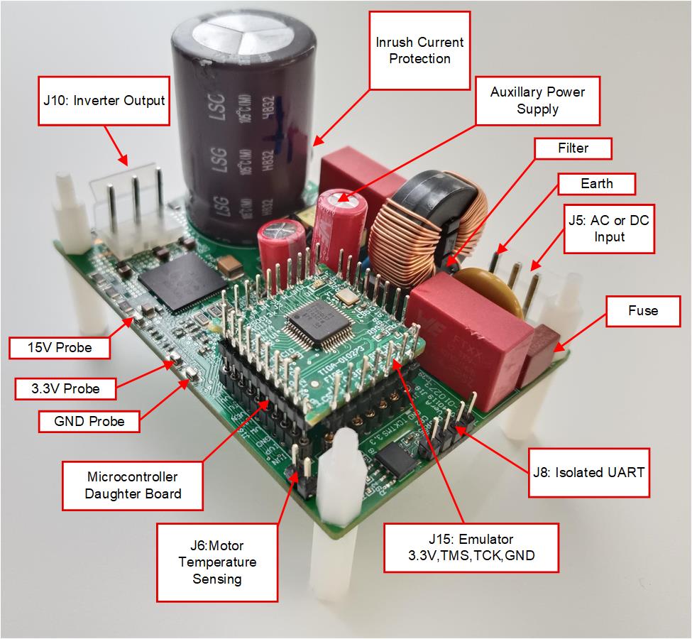
The reference board has functional groups that enable a complete motor drive system. The following is a list of the blocks (and functions) on the board, Figure 3-2 shows the top view of the board and different blocks of the TIDA-010273 board.
- Power line input filter
- 3-phase inverter
- Up to 250W 3-phase inverter supports PMSM or IPM
- 15kHz switching frequency
- 1-3 shunts current sensing
- Control
- Single TMS320F2800137 or MSPM0G1507 series MCU in 48-pin LQFP package
- Amplify and input filters for the analog signals
- Interface for external motor temperature sensing
- Isolated UART port
- Auxiliary power supply
- Onboard power supply +3.3V, and +15V
 Figure 3-2 TIDA-010273 Reference Design Board Layout
TI recommends taking the following precautions when using the board:
WARNING:
- Do not touch any part of the board or components connected to the board when the board is energized.
- Use the AC Mains or wall power supply to power the kit. TI recommends an isolation AC source.
- Do not touch any part of the board, the kit or the assembly when energized. (Though the power module heat sink is isolated from the board, high-voltage switching generates some capacitive coupled voltages over the heat sink body.)
- Control Ground can be hot.