TIDUF84 June   2024


  1.   1
  2.   Description
  3.   Resources
  4.   Features
  5.   Applications
  6.   6
  7. 1System Description
    1. 1.1 Key System Specifications
  8. 2System Overview
    1. 2.1 Block Diagram
    2. 2.2 Design Considerations
    3. 2.3 Highlighted Products
      1. 2.3.1 UCC28810
      2. 2.3.2 MCF8315
      3. 2.3.3 MSPM0L
      4. 2.3.4 MSPM0C
  9. 3System Design Theory
    1. 3.1 MCF8315 Design
      1. 3.1.1 Power section
      2. 3.1.2 GPIO section
    2. 3.2 ACDC Design: Single Stage PFC
    3. 3.3 Host MCU Design
  10. 4Hardware, Software, Testing Requirements, and Test Results
    1. 4.1 Hardware Requirements
      1. 4.1.1 Hardware Overview
      2. 4.1.2 TIDA-010951 PCB
    2. 4.2 Software Requirements
    3. 4.3 Testing requirements
    4. 4.4 Test Setup
    5. 4.5 Test Results
      1. 4.5.1 Power Management in TIDA-010951
      2. 4.5.2 UCC28810 Based Single Stage PFC
      3. 4.5.3 BLDC Residential Fan Operation Using MCF8315C
        1. 4.5.3.1 Power-Up Sequence
        2. 4.5.3.2 Forward Windmilling (ISD Forward Resync)
        3. 4.5.3.3 Reverse Windmilling (ISD Reverse Resync)
        4. 4.5.3.4 Direction Reversal
        5. 4.5.3.5 Fan Acceleration/Deceleration
      4. 4.5.4 Thermal Performance
  11. 5Design and Documentation Support
    1. 5.1 Design Files
      1. 5.1.1 Schematics
      2. 5.1.2 BOM
    2. 5.2 Tools and Software
    3. 5.3 Documentation Support
    4. 5.4 Support Resources
    5. 5.5 Trademarks
  12. 6About the Author
  13. 7Recognition

Thermal Performance

Figure 4-12 and Figure 4-13 shows the maximum case temperature of the key power dissipating components on TIDA-010951. The test conditions are – 250C ambient, passive cooling, 230VAC RMS input, 1A motor phase currents. The thermal images were captured after 30 minutes of continuous operation at the aforementioned test conditions.
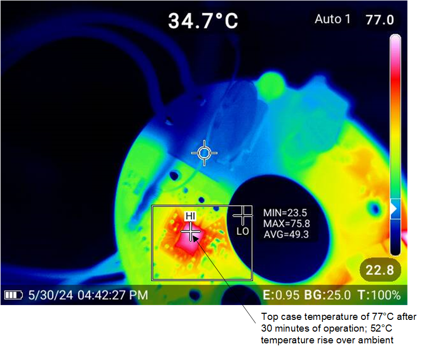
TIDA-010951 Thermal Performance of
                    MCF8315C Figure 4-12 Thermal Performance of MCF8315C
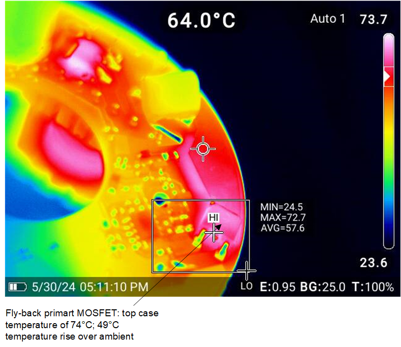
TIDA-010951 Thermal Performance of Power
                    Supply Figure 4-13 Thermal Performance of Power Supply