TIDUF87 November 2024
- 1
- Description
- Resources
- Features
- Applications
- 6
- 1System Description
- 2System Overview
-
3Hardware, Software, Testing Requirements, and Test Results
- 3.1 Hardware Requirements
- 3.2 Software Requirements
- 3.3 Test Setup
- 3.4
Test Procedure
- 3.4.1 Lab Variables Definitions
- 3.4.2 Lab 1. Open-Loop Current Control Single Phase
- 3.4.3 Lab 2. Closed Loop Current Control Single Phase
- 3.4.4 Lab 3. Open Loop Voltage Control Single Channel
- 3.4.5 Lab 4. Closed Loop Current and Voltage Control Single Channel
- 3.4.6 Lab 5. Closed Loop Current and Voltage Control Four Channels
- 3.4.7 Calibration
- 3.5 Test Results
- 4Design and Documentation Support
- 5About the Author
3.2.2 Project Structure
Figure 3-3 shows the general structure of the project. Once the project is imported, the Project Explorer appears inside CCS as shown in Figure 3-4.
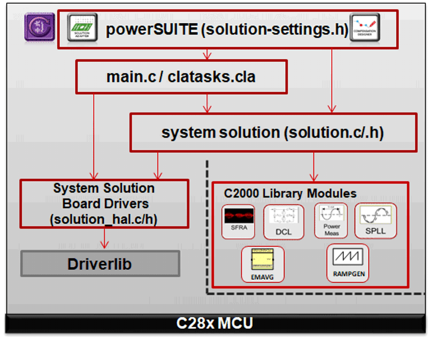 Figure 3-3 Project Structure Overview
Solution-specific and device-independent files
that consist of the core algorithmic code are in .c/h.
Board-specific and device-specific files are in
_hal.c/h. This file consists of device-specific drivers to run
the solution. If the user wants to use a different modulation scheme or a different
device, the user is required only to make changes to these files, besides changing
the device support files in the project.
The -main.c file consists of the
main framework of the project. This file consists of calls to the board and solution
file that help in creating the system framework, along with the interrupt service
routines (ISRs) and slow background tasks.
For this design, the solution is
bt4ch_gan.
The powerSUITE page can be opened by clicking on
the main.syscfg file, listed under the Project Explorer. The
powerSUITE page generates the _settings.h file. This file is the
only C language based file used in the compile of the project that is generated by
the powerSUITE page. The user must not modify this file manually, because the
changes are overwritten by powerSUITE each time the project is saved.
_user_settings.h is included by the
_settings.h file and can be used to keep any settings that are
outside the scope of powerSUITE tools such as #defines for ADC
mapping, GPIOs, and so forth.
The _cal.h file consists of gain and offset values for current and voltage measurements.
The Kit.json and
solution.js files are used internally by powerSUITE, and must
not be modified by the user. Any changes to these files results in the project not
functioning properly.
The solution name is also used as the module name for all the variables and defines used in the solution. Hence, all variables and function calls are prepended by the BT4CH name (for example, BT4CH_userParam_chX). This naming convention lets the user combine different solutions while avoiding naming conflicts.
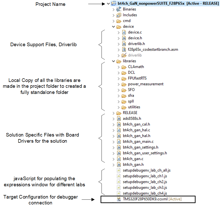 Figure 3-4 Project Explorer View of the BT4PH Project
The bt4ch_gan project consists of three ISRs (ISR1, ISR2, and ISR3).
ISR1 is used to sense the input supply voltage and output capacitor voltage of the buck converters. ISR1 is triggered by ADCC conversion complete. ADCC senses input voltage and output voltage of the converters, and the output is used to implement soft-start of the DC/DC.
ISR2 is triggered by the BUSY signal of the ADS8588S. The external ADC is programmed for a 50kSPS sample rate, which sets the ISR frequency.
ISR3 is triggered by SPI receive FIFO interrupt. The ISR is used to read the external ADC data from FIFO registers, and run the control loop functions.
Figure 3-5 shows the time taken by ISR1, ISR2, and ISR3 when all four channels are ON. The total time taken three ISRs is less than 6μs that is less 30% of CPU usage for 50kSPS control loop sample rate. Figure 3-6 and Figure 3-7 show ISR time for when only one channel is ON and all channels are OFF.
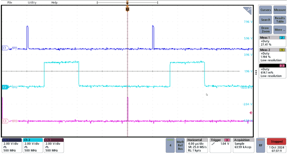 Figure 3-5 ISR Execution Time for Four Channels
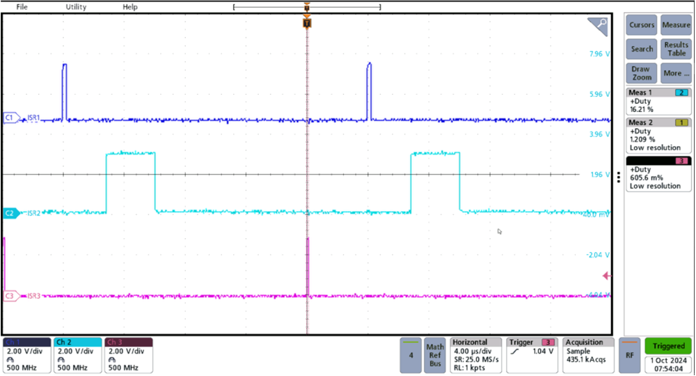 Figure 3-6 ISR Execution Time for One Channel
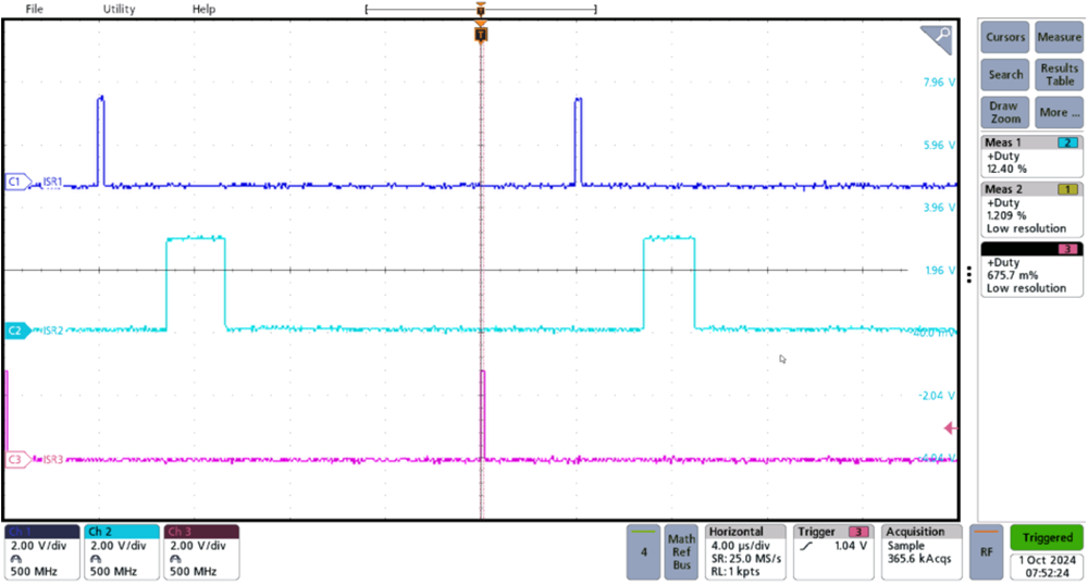 Figure 3-7 ISR Execution Time When All
Channels are OFF