TIDUF91 December 2024
4.1 Hardware Requirements
The TIDA-020075 is categorized into two sections to explain the design in terms of the application:
- Driver
- Power and connectors
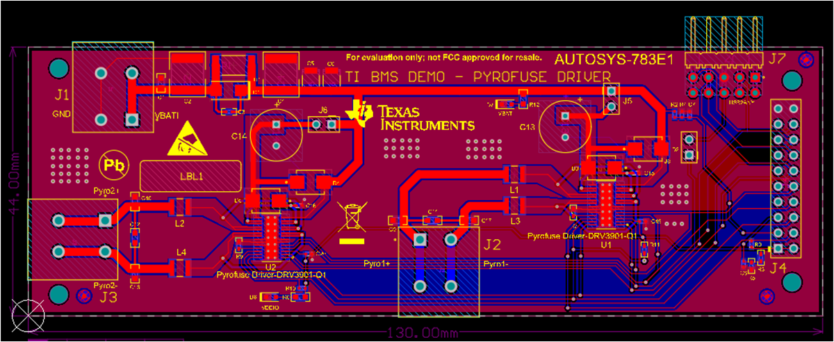
TRG1 and TRG2 is the DRV3901-Q1 hardware trigger. The device can also be triggered with SPI. J5 and J6 are not connected as default and are not needed for the final customer design. The device needs to be connected only when the D2 and D4 connections were broken. A local energy reservoir capacitor on VREG is required to supply the driver in loss of PVDD power supply fault condition.
Figure 4-3 shows where different pin headers, LEDs, and connectors are located on the PCB.
There are 2 LEDs to indicate the state of the power. D6 lights on if VOOIO is power on, D7 lights on if VBATI is power on.
For connectors, J1 is the input of VBATI, J2 and J3 are the output of pyro-fuse driver. J7 is the USB2ANY port and can be used to configure and trigger DRV3901-Q1. J4 is the port connect with another demonstration board – the bus controller unit (BCU) board – the controller board of the BMS system.
 Figure 4-1 TIDA-020075 Schematic:
Driver
 Figure 4-2 TIDA-020075 Schematic: Power
and Connectors
 Figure 4-3 TIDA-020075 PCB Layout Top