SLAA984A November 2020 – January 2021 MSP430FR2433
1 TI Tech Note
Introduction
The programmable system wake-up controller function of the MSP430FR2433 microcontroller (MCU) offers a simple way to add an external, real-time, and low power wake-up controller to an existing system. This type of system wake-up controller is useful to applications that need to stay in low-power modes for variable extended periods of time. To get started, download project files and a code example demonstrating this functionality.
Implementation
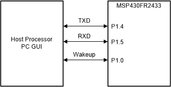
A low-frequency 32.768-kHz crystal is required for this application. The host MCU/PC GUI can send the wake-up time through universal asynchronous receiver/transmitter (UART) to MSP430FR2433. At this point, the host should go into a low-power or sleep mode as the real-time clock (RTC) starts immediately after reception of time data. When the wakeup timer counts down to zero, the MSP430FR2433 will toggle the P1.0 to wake up the host MCU and will send back a wakeup signal to the GUI (see Figure 1-1).
 Figure 1-1 Programmable System Wake-up
Controller Block Diagram
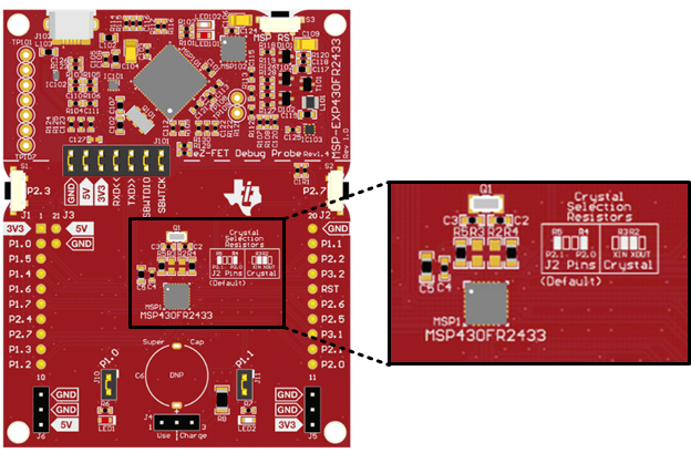
 Figure 1-2 MSP430FR2433 Resistor
Selection for Onboard 32-kHz Crystal
Figure 1-2 MSP430FR2433 Resistor
Selection for Onboard 32-kHz CrystalThe wake-up time is a function of the RTC Counter peripheral and software scaling factors. The RTC Counter module in this application is clocked by XT1 at approximately 32.768 kHz. The largest pre-divider for the module is 1024. By using this divider value, every 32 counts of the RTC Counter is 1 second. The RTCMOD register holds a count value that gives an interrupt when the RTC Counter counts to it. The RTCMOD register of the RTC Counter is 16 bits wide so the maximum that time the RTC Counter can count before overflow is approximately 34 minutes. The RTCMOD is set as 31 and fixed in this example, which provides an interrupt every second. The wake-up time defines as an unsigned int8 format. It allows the customer to set the wakeup time from 1s to 255s in the example code. For example, if a host wanted to setup a wake-up time of 60 seconds, it would send a value of 0x3C over UART.
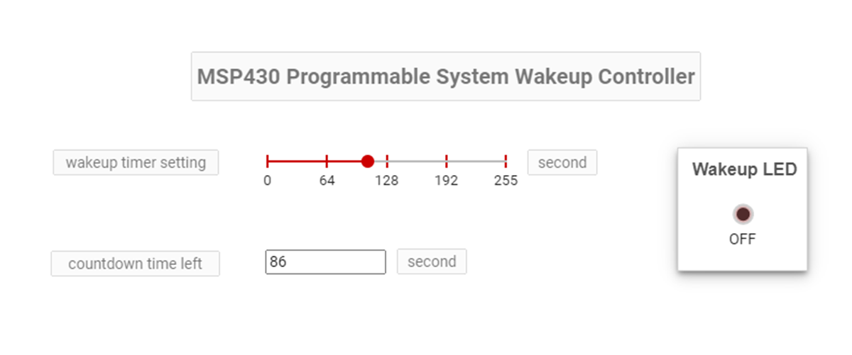
The programmable wake-up controller is design to stay in low-power mode 3 (LPM3) to conserve power. When the host controller sends the wake-up time data, the RTC starts counting to the time value sent to the device. The RTC interrupt manages the total wake-up time and sends a low-to-high pulse to the host controller after the time value has been reached. The MSP430 MCU also sends the countdown time left data to the GUI (see Figure 1-3). Host MCU and GUI can change the wakeup time by sending a new value to the MSP430 MCU at any time. The MSP430 MCU reconfigures the wake-up timer settings when it receives a new data.
 Figure 1-3 Programmable System Wake-Up
Controller GUI
Figure 1-3 Programmable System Wake-Up
Controller GUIPerformance
The average power consumption of the programmable system wake-up controller is around 1.3 μA. The average current of the application is dominated by the LPM3 current of the device and approaches this level as the wake-up time period is extended.
To Get Started
- Watch our training video “Programmable Wake Up Controller with a Housekeeping MCU”, where we walk through how to use a GUI to wake up the MCU after an elapsed amount of time.
- Order an MSP430FR2433 LaunchPad kit to evaluate the Programmable Wake Up Controller example code.
- Download and test this example with the Programmable Wake-Up Controller example GUI.
- Evaluate the Programmable Wake-Up Controller example code for the MSP430FR2433 LaunchPad kit.
Device Recommendations
| Part Number | Key Features |
|---|---|
| MSP430FR2433 | 16KB FRAM, 4KB SRAM, 10-bit ADC, UART/SPI/I2C, Timer |
| MSP430FR2422 | 8KB FRAM, 2KB SRAM, 10-bit ADC, UART/SPI/I2C, Timer |