-
ISO154xEVM Low-Power Bidirectional I2C Isolators Evaluation Module SLLU166A June 2012 – September 2022 ISO1540 , ISO1540-Q1 , ISO1541 , ISO1541-Q1
-
ISO154xEVM Low-Power Bidirectional I2C Isolators Evaluation Module
ISO154xEVM Low-Power Bidirectional I2C Isolators Evaluation Module
1 Introduction
This User’s Guide details the ISO154x Evaluation Module (EVM) operation of the factory-installed ISO1540 and ISO1541 I2C-compatible bidirectional isolators. The EVM may be reconfigured for use with two ISO1540 or two ISO1541 instead of one of each.
This Guide presents a typical laboratory setup used with this EVM.
This Evaluation Module (EVM) is made available for isolator parameter performance evaluation only and is not intended for isolation voltage testing. To prevent damage to the EVM, any voltage applied as a supply or digital input/output must be maintained within the 0 V to 5.5 V recommended operating range.
Exceeding the specified input voltage range may cause unexpected operation and irreversible damage to the EVM. If there are questions concerning the input voltage range, contact a TI field representative prior to connecting power.
Applying loads outside the specified output range may result in unintended operation and possible permanent damage to the EVM. If there is uncertainty as to the load specification, contact a TI field representative.
1.1 Overview
The ISO154x devices are low-power, bidirectional isolators that are compatible with I2C interfaces. The logic input and output buffers on these devices are separated by TI’s Isolation technology utilizing a silicon dioxide (SiO2) barrier. When used in conjunction with isolated power supplies, these devices block high voltages, isolate grounds and prevent noise currents from entering the local ground and interfering with or damaging sensitive circuitry.
The ISO1540 has two isolated bidirectional channels for clock and data lines and is fit for multi-master applications. The ISO1541 has a bidirectional data and a unidirectional clock channel and is useful in applications that have a single master.
These devices achieve isolated bidirectional communication by introducing an offset, making the side 1 low-level output greater than the side 1 low-level input and thus preventing an internal logic latch that otherwise would occur with standard digital isolators.
1.3 Functional Configuration
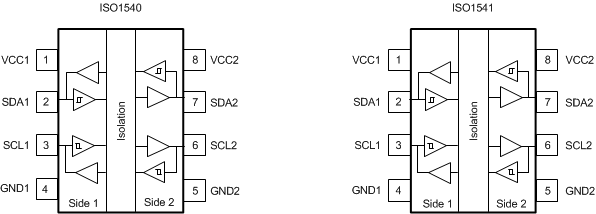
The pinouts of ISO1540 and ISO1541 are displayed in Figure 1-1. These devices have an input noise-filter that prevents transient pulses of up to 5 ns from being passed to the output of the device.
 Figure 1-1 ISO1540 and ISO1541 Pinout
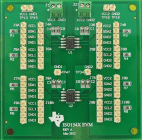
The EVM is shown in Figure 1-2, it comes with an ISO1540 and an ISO1541 installed in place of U1 and U2 respectively. However, this EVM can be configured for use with two ISO1540s or two ISO1541s.
 Figure 1-2 ISO154xEVM Top Photograph
An input or output pin can be tied either to supply voltage (VCCx) or Ground (GNDx) using the 4-pin jumpers on the EVM (J3A to J10A on side 1 and J3B to J10B on side 2). These jumpers also provide scope-probe access to each pin.
Each signal line (SDAx, SCLx) is configured with a 1-kΩ pull-up resistor (R1 to R8) to the corresponding power supply (VCCx). Reconfigure the value of this pull-up resistor as per the application requirement.