-
LMX2615EVM-CVAL Wideband 15-GHz Synthesizer
- LMX2615EVM-CVAL Wideband 15-GHz Synthesizer
- Trademarks
- 1 Evaluation Board Setup and Description
- 2 Setting Up the Software
- 3 Bringing LMX2615 to a Lock State
- 4 Current Loop Filter Configuration
- 5 Typical Phase Noise
- 6 Schematic
- 7 Bill of Materials
- 8 PCB Specifications
- 9 Proper Jumper and Switch Positions
- 10Revision History
- IMPORTANT NOTICE
EVM USER'S GUIDE
LMX2615EVM-CVAL Wideband 15-GHz Synthesizer
1 LMX2615EVM-CVAL Wideband 15-GHz Synthesizer
 Figure 1-1 LMX2615EVM-CVAL
Trademarks
All trademarks are the property of their respective owners.
1 Evaluation Board Setup and Description
 Figure 1-1 LMX2615EVM Setup and Description
- Power:
- Set power supply to 3.3 V with 600-mA current limit and connect to VCC SMA.
- Input Signal
- The EVM is designed for a 100-MHz input reference that should be connected to the OSCin SMA. Some of the options for this could be a signal generator, the 100 MHz output from the Reference Pro board, or a very clean signal source such as the Wenzel 501-4623G ultra-low phase noise 100 MHz reference
- Programming Interface:
- Reference Pro will provide SPI interface to program LMX2615. If using this, Connect USB cable from laptop or PC to USB port in Reference Pro. This provides power to Reference Pro Board and communication with TICS GUI
- The other option is to use the dip switch on the board to use Pin mode.
- Output:
- Connect RFoutAP to a phase noise analyzer and connect a 50-Ω terminator to RFoutAM.
2 Setting Up the Software
- Download the TICS Pro from the TI Website at www.ti.com/tool/TICSPRO-SW and install.
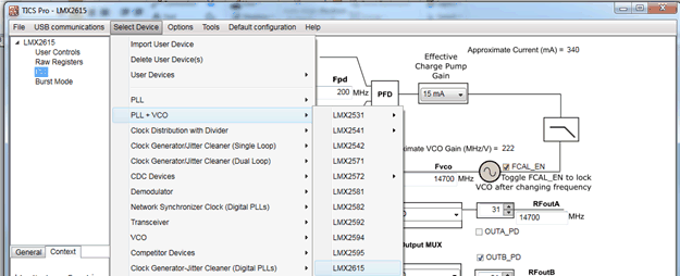
- From the menu bar choose Select Device → PLL + VCO → LMX2615
 Figure 2-1 Search for LMX2615 on TICS Pro
 - Verify the communication setup with Reference Pro. To do this, select USB communications → Interface . Click on the identify button and the LED on the Reference Pro should blink.