-
Real-time Control Meets Real-time Industrial Communications Development – Part 4
Real-time Control Meets Real-time Industrial Communications Development – Part 4
Christopher Chiarella

Part 1 of this blog series gave an overview of the market opportunities for EtherCAT slave stack support on C2000™ microcontrollers (MCUs) and an introduction to a three-phased solution to jump-start slave stack development. Part 2 detailed what’s different and compelling about the TI C2000 MCU EtherCAT implementation. Part 3 broke down the three phases of development for your own slave-node application using the EtherCAT slave and C2000 Delfino MCU controlCARD kit, and how the TI EtherCAT package in C2000 controlSUITE™ software supports each phase. In part 4 of this series, I will step through the development of your own EtherCAT slave controller using the latest C2000 TMS320F28388D real-time controller.
The C2000 F28388D MCU has the EtherCAT peripheral from Beckhoff integrated onto the chip. The EtherCAT peripheral ownership can be allocated to CPU1 or CM. To support this, a set of software solutions have been released into C2000Ware, the software package for C2000 MCUs. These F28388D EtherCAT software solutions will help you:
- Validate the correct EtherCAT operation of your F28388D ControlCARD or custom F28388D board.
- Evaluate the EtherCAT slave stack and create a slave-node application using the F28388D.
Getting Started
To get started evaluating and experimenting with EtherCAT on F28388D, you’ll need to download and install:
- C2000Ware – contains all of the EtherCAT software for the F28388D.
- EtherCAT Master Software (Select one from below)
- Option 1: TwinCAT PC/PLC – the Beckhoff EtherCAT master.
- Option 2: EC-Engineer – the Acontis EtherCAT master.
For F28388D EtherCAT example code and more detailed usage documentation beyond what is described here, navigate within C2000Ware to ~\C2000Ware_X_XX_XX_XX\libraries\communications\Ethercat\f2838x.
Validating Operation and Connections
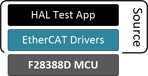
The F28388D EtherCAT software solution includes a set of hardware abstraction layer (HAL) test applications (one for CPU1 and one for CM) that exercise the ASYNC16 processor data interface (PDI) between the EtherCAT subsystem and device central processing unit in order to perform a series of reads and writes to EtherCAT registers and memory. The software stack for this application is detailed in Figure 1. Additionally, these applications include checks to confirm that the device’s electrically erasable programmable read-only memory (EEPROM) is programmed with the required minimum set of data that EtherCAT needs.
 Figure 1 F28388D EtherCAT HAL test application
You don’t need the EtherCAT slave stack to perform this validation. Once you’ve loaded this application onto the device, an EtherCAT master will be able to identify the EtherCAT slave controller on the network, which will confirm that the physical interfaces are working. From here, you can program the EEPROM for the EtherCAT slave and then rerun the application to perform the PDI checks described earlier.
Evaluating the EtherCAT Slave-node Solution
The F28388D EtherCAT software solution includes both an EtherCAT slave demo as well as a reference solution. Both include a variant for running from CPU1 or from CM.
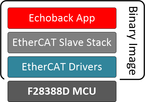
The EtherCAT slave demo application is a simple “echoback” example, where data sent from the EtherCAT master is received by the EtherCAT slave controller and sent back to the master. The demo application software stack is depicted in Figure 2. Using the TwinCAT PC software for the EtherCAT master node, you can set up a multinode EtherCAT network in minutes on your bench.
 Figure 2 F28388D EtherCAT Echoback Demo App
The demo application is provided as a binary image and is configured for the F28388D controlCARD. The EtherCAT slave stack is integrated into the image; therefore, you don’t need to generate the slave stack code yourself. All you need to do is program the F28388D controlCARD with the application and connect a CAT5 cable from the controlCARD to the EtherCAT master (in this case, TwinCAT PC/PLC).
Creating Your Own EtherCAT Slave-node Solution
After evaluating using the EtherCAT slave demo application, the F28388D EtherCAT software includes a reference solution for creating your own slave-node application.
The EtherCAT slave reference solution is setup to perform the same echoback functionality as the demo. This solution, however, includes all of the necessary source code (except for the EtherCAT slave stack itself) for debugging the solution and developing it into your own application. Figure 3 details the software stack for the solution. You can obtain the EtherCAT slave stack code through the EtherCAT Technology Group’s (ETG) slave stack code (SSC) ET9300 tool.
 Figure 3 F28388D EtherCAT echoback solution with the ETG slave stack
To generate slave stack code for F28388D devices, a configuration file is provided within the F28388D EtherCAT software solution package that, once imported into the SSC tool, will make the F28388D stack configurations available via the tool’s drop-down menu. Upon selection of a configuration, the tool will generate the slave stack source code for integrating into the solution. The F28388D EtherCAT software usage documentation within C2000Ware provides further details.
Once the slave stack is generated and linked into the F28388D EtherCAT slave reference solution, you’re ready to start running the solution and developing it into your own EtherCAT slave application.
Download C2000Ware today and jump-start your development of an EtherCAT slave controller with the C2000 F28388D MCU.
Additional resources:
- Purchase the C2000 F28388D controlCARD
- To learn more about TI’s EtherCAT slave-node solutions for C2000 MCUs, check out:
IMPORTANT NOTICE AND DISCLAIMER
TI PROVIDES TECHNICAL AND RELIABILITY DATA (INCLUDING DATASHEETS), DESIGN RESOURCES (INCLUDING REFERENCE DESIGNS), APPLICATION OR OTHER DESIGN ADVICE, WEB TOOLS, SAFETY INFORMATION, AND OTHER RESOURCES “AS IS” AND WITH ALL FAULTS, AND DISCLAIMS ALL WARRANTIES, EXPRESS AND IMPLIED, INCLUDING WITHOUT LIMITATION ANY IMPLIED WARRANTIES OF MERCHANTABILITY, FITNESS FOR A PARTICULAR PURPOSE OR NON-INFRINGEMENT OF THIRD PARTY INTELLECTUAL PROPERTY RIGHTS.
These resources are intended for skilled developers designing with TI products. You are solely responsible for (1) selecting the appropriate TI products for your application, (2) designing, validating and testing your application, and (3) ensuring your application meets applicable standards, and any other safety, security, or other requirements. These resources are subject to change without notice. TI grants you permission to use these resources only for development of an application that uses the TI products described in the resource. Other reproduction and display of these resources is prohibited. No license is granted to any other TI intellectual property right or to any third party intellectual property right. TI disclaims responsibility for, and you will fully indemnify TI and its representatives against, any claims, damages, costs, losses, and liabilities arising out of your use of these resources.
TI’s products are provided subject to TI’s Terms of Sale (www.ti.com/legal/termsofsale.html) or other applicable terms available either on ti.com or provided in conjunction with such TI products. TI’s provision of these resources does not expand or otherwise alter TI’s applicable warranties or warranty disclaimers for TI products.
Mailing Address: Texas Instruments, Post Office Box 655303, Dallas, Texas 75265
Copyright © 2023, Texas Instruments Incorporated