-
Powering the Smart Home with a Simple Charger
Powering the Smart Home with a Simple Charger
Advancements in wireless connectivity and low-power embedded processing technology have enabled new applications for smart homes and buildings. Of course, most smart home systems have a control panel or base unit in a fixed location that plugs into the AC power system. But there may also be a number of distributed (and movable) wireless sensors or cameras that are part of the overall system. These peripheral devices are not always near a permanent power source. Figure 1 shows a typical system with multiple remote peripheral devices and a central gateway (controller).
 Figure 1 Example of a Smart
Home
Figure 1 Example of a Smart
HomeMany of these wireless sensors or cameras will need batteries and frequent use requires regular battery replacement, adding to maintenance costs over time. As a result, rechargeable batteries are becoming more popular for these modular accessories. In some cases, the control panel unit has a battery as well to provide backup power or an alarm in case of AC power failure.
If you are developing a smart home system, you probably want to focus your efforts on system functionality and not the basic task of power supply and recharging. Since lithium-ion batteries have become so common in recent years, there are numerous choices for dedicated battery-charging IC solutions.
For small batteries and low charge currents, you can use a cost-effective (and relatively easy to implement) linear charger. But higher-performance peripheral devices such as high-resolution cameras may need a larger battery to ensure long run times. That means you’ll need more charge current, which will require a switch-mode charger. Otherwise, the amount of heat generated due to power loss in a linear charger will be excessive.
Unfortunately, many higher-current switch-mode chargers require software control from a host processor – which is an additional investment of engineering time on your part. The benefit of these programmable chargers is that you have the flexibility to adapt the circuit to different battery types and charging currents. Other switch-mode chargers may require external power FETs or current-sensing components to enable variable charge currents.
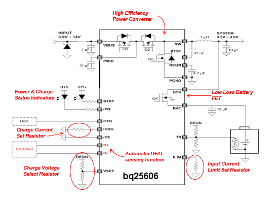
How can you have an adjustable, flexible solution for different battery types without having to invest in software development or lay out a complex PCB? This is where the bq25606 charger comes in. The circuit shown in Figure 2 provides all of the functionality needed for a typical single-cell charging and system power solution. The bq25606 enables you to optimize your charge current as well as the battery terminal voltage with just a couple of resistor values. It also has built-in overvoltage protection to guard against power line or connection transients, and can automatically detect the power available from most standard USB power sources.
You can adjust the input current limit and charging current and set the battery voltage (4.2V, 4.35V or 4.4V as needed for a given battery type) with just a few simple external component selections. If you need an easy-to-use, general-purpose battery-charging solution, “smart” doesn’t have to be complicated.
 Figure 2 bq25606 Implementation Schematic
In a dynamic and evolving market, the success of your end product may depend getting to market faster than the competition. Assuming that you are using a standard type of Li-Ion power source, you can use a simple, ready-to-go standalone charging solution to save time compared to a developing a customized or programmable solution. With the bq25606, you can optimize the charge current and voltage settings with a few simple component selections and be up and running in minutes!
Additional Resources:
- Read more battery blogs.
- Watch the trainings:
- Discover more resources for building automation, IP cameras and video doorbells.
IMPORTANT NOTICE AND DISCLAIMER
TI PROVIDES TECHNICAL AND RELIABILITY DATA (INCLUDING DATASHEETS), DESIGN RESOURCES (INCLUDING REFERENCE DESIGNS), APPLICATION OR OTHER DESIGN ADVICE, WEB TOOLS, SAFETY INFORMATION, AND OTHER RESOURCES “AS IS” AND WITH ALL FAULTS, AND DISCLAIMS ALL WARRANTIES, EXPRESS AND IMPLIED, INCLUDING WITHOUT LIMITATION ANY IMPLIED WARRANTIES OF MERCHANTABILITY, FITNESS FOR A PARTICULAR PURPOSE OR NON-INFRINGEMENT OF THIRD PARTY INTELLECTUAL PROPERTY RIGHTS.
These resources are intended for skilled developers designing with TI products. You are solely responsible for (1) selecting the appropriate TI products for your application, (2) designing, validating and testing your application, and (3) ensuring your application meets applicable standards, and any other safety, security, or other requirements. These resources are subject to change without notice. TI grants you permission to use these resources only for development of an application that uses the TI products described in the resource. Other reproduction and display of these resources is prohibited. No license is granted to any other TI intellectual property right or to any third party intellectual property right. TI disclaims responsibility for, and you will fully indemnify TI and its representatives against, any claims, damages, costs, losses, and liabilities arising out of your use of these resources.
TI’s products are provided subject to TI’s Terms of Sale (www.ti.com/legal/termsofsale.html) or other applicable terms available either on ti.com or provided in conjunction with such TI products. TI’s provision of these resources does not expand or otherwise alter TI’s applicable warranties or warranty disclaimers for TI products.
Mailing Address: Texas Instruments, Post Office Box 655303, Dallas, Texas 75265
Copyright © 2023, Texas Instruments Incorporated