A Simple and Efficient LED Driver for Video Surveillance Cameras
Mark Allen Esquillo

Video surveillance security monitoring is in demand, and the technology has also become more affordable for both personal and commercial use. Compelled by the need for better security, millions of security cameras have been installed worldwide.
Because many security cameras are on all the time, it is no surprise that surveillance camera manufacturers have moved to energy-saving light-emitting diode (LED) lighting. Compared to previous incandescent/fluorescent lamps, LEDs provide 80-90% more efficiency, with lower heat dissipation. LEDs also have a longer life span and require less space when implemented in video surveillance cameras.
With volumes ramping up, camera makers have clamored for LED driver board designs to be more simple, more compact and cost less. But at the same time, they need the LED drivers to have high efficiency for lower power consumption, and higher accuracy for better image resolution. Given these challenges, hardware engineers need an LED driver solution that checks off all of these requirements.
TI’s TPS54200 is a new DC/DC synchronous buck LED driver that helps support video surveillance and other end equipment. The device offers an efficient and cost-effective solution with high analog dimming accuracy. The TPS54200 is available in a simple small-outline transistor (SOT)23-6 package, enabling users to easily design LED driver boards.
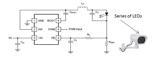
Figure 1 shows a simplified schematic of the TPS54200 driving a series of white LEDs with the absolute lowest amount of external components. It would be a great solution for video surveillance cameras or other general-purpose LED lighting for commercial/industrial use.
 Figure 1 Simplified Schematic of the
TPS54200
Figure 1 Simplified Schematic of the
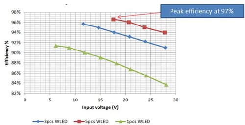
TPS54200The TPS54200 has low RDS(on) for high efficiency when driving LEDs in strings. Flip-chip-on-lead (FCOL) technology minimizes inductance and resistance between the die and the package leads. With its low on-resistance, the device is able to operate with high efficiency (97% peak efficiency) and keep surveillance camera power consumption as low as possible. See Figure 2.
 Figure 2 TPS54200 Efficiency at a 1A
Load
Figure 2 TPS54200 Efficiency at a 1A
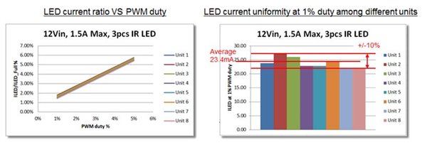
LoadTI designed the analog dimming function of the TPS54200 to have very good accuracy, which enables the current running through the LED to be proportional to the pulse-width modulation (PWM) duty ratio with excellent linearity. Pls. refer to Figure 3 Thus, you can make the microcontroller unit (MCU) generate PWM pulses with higher accuracy than typical dimming through a DC voltage.
 Figure 3 100% Linearity of LED Current
against PWM Duty
Figure 3 100% Linearity of LED Current
against PWM DutyWith the TPS54200, it’s possible to drive a series of LEDs at an exceptionally high brightness accuracy through the PWM input – even at a 5% PWM duty ratio. This is a huge benefit for end-equipment designers who would like to ensure accurate brightness control, even when using untrimmed LEDs for a lower-cost implementation. See Figure 4.
 Figure 4 TPS54200 LED Current Accuracy
Test with Untrimmed White LEDs
Figure 4 TPS54200 LED Current Accuracy
Test with Untrimmed White LEDsIn keeping with the current global trend of moving to LED lighting for better power consumption, the TPS54200 can drive a series of white LEDs in a simple, easy-to-use and cost-effective design with high brightness control capability. Video surveillance camera makers and other end-equipment manufacturers that need a simple LED driver for series LED lighting would appreciate such a solution. Get more information on designing video surveillance cameras.
IMPORTANT NOTICE AND DISCLAIMER
TI PROVIDES TECHNICAL AND RELIABILITY DATA (INCLUDING DATASHEETS), DESIGN RESOURCES (INCLUDING REFERENCE DESIGNS), APPLICATION OR OTHER DESIGN ADVICE, WEB TOOLS, SAFETY INFORMATION, AND OTHER RESOURCES “AS IS” AND WITH ALL FAULTS, AND DISCLAIMS ALL WARRANTIES, EXPRESS AND IMPLIED, INCLUDING WITHOUT LIMITATION ANY IMPLIED WARRANTIES OF MERCHANTABILITY, FITNESS FOR A PARTICULAR PURPOSE OR NON-INFRINGEMENT OF THIRD PARTY INTELLECTUAL PROPERTY RIGHTS.
These resources are intended for skilled developers designing with TI products. You are solely responsible for (1) selecting the appropriate TI products for your application, (2) designing, validating and testing your application, and (3) ensuring your application meets applicable standards, and any other safety, security, or other requirements. These resources are subject to change without notice. TI grants you permission to use these resources only for development of an application that uses the TI products described in the resource. Other reproduction and display of these resources is prohibited. No license is granted to any other TI intellectual property right or to any third party intellectual property right. TI disclaims responsibility for, and you will fully indemnify TI and its representatives against, any claims, damages, costs, losses, and liabilities arising out of your use of these resources.
TI’s products are provided subject to TI’s Terms of Sale (www.ti.com/legal/termsofsale.html) or other applicable terms available either on ti.com or provided in conjunction with such TI products. TI’s provision of these resources does not expand or otherwise alter TI’s applicable warranties or warranty disclaimers for TI products.
Mailing Address: Texas Instruments, Post Office Box 655303, Dallas, Texas 75265
Copyright © 2023, Texas Instruments Incorporated