-
How to Design a Limited Power Source Industrial AC/DC Power Supply with Minimal Components – Part 2
How to Design a Limited Power Source Industrial AC/DC Power Supply with Minimal Components – Part 2
Latif Ameer
Part one of this blog discussed basic needs of a Limited Power Source (LPS) and provided a brief overview of standards that govern LPS circuits.
To address the needs of protection and limiting, conventional power supplies as illustrated in Figure 1 rely on multiple feedback loops based on two or more optocouplers. These optocouplers transmit the load voltage, load current and open-fault information to the main controller – typically a flyback controller for wattages up to 150W. In addition, the current-sensing circuitry has external current-sense resistors, precision operational amplifiers for amplification and setting the constant current-constant voltage (CC-CV), and constant power feedback loops. Overall, discrete circuits have high component counts, use up valuable real estate on the board and add cost to the system.
 Figure 1 Typical Block Diagram Showing
the Conventional Architecture of a 100W Industrial Power Supply
Figure 1 Typical Block Diagram Showing
the Conventional Architecture of a 100W Industrial Power SupplyFigure 2 shows a proposed design architecture with reduced feedback loops. The architecture uses the UCC28740, a CC-CV flyback controller with optocoupled feedback for voltage and primary-side regulation (PSR) for constant current. The high level of integration of the controls in the UCC28740 controller aids in low component count design and reduced cost.
 Figure 2 Proposed Design Architecture
with Reduced Feedback Loops
Figure 2 Proposed Design Architecture
with Reduced Feedback LoopsThe two key benefits of this proposed architecture are:
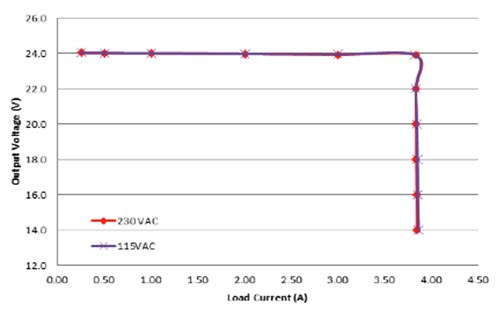
- Precise current and power limit, just with primary-side sensing. In the conventional approach shown in Figure 1,The output load current is sensed through discrete operational amplifier circuits and transmitted to main controller through opto-coupler. In some cases an additional opto-coupler is used for feedback redundancy. the output load current is directly sensed and the information is fed back to the flyback controller through a separate optocoupler circuit. The proposed architecture, on the other hand, uses cost-effective and reliable primary-side current sensing. A high degree of precision in the output-current limit is made possible by precision PSR current-sense techniques embedded into the UCC28740. The current limit causes the voltage foldback and ensures tight power limiting.
- Cost-effective open-loop protection and feedback redundancy. The conventional approach shown in Figure 1 uses two feedback loops, both of which are based on optocouplers. The identical nature of these optocouplers and their associated circuitry bring in an additional risk of failure; each of the optocouplers can fail simultaneously under similar stress conditions, which can be detrimental.
The proposed architecture uses a single optocoupler feedback precision-output voltage control. A PSR circuit provides a redundant voltage-control loop. PSR activates during open-loop conditions such as failure in the optocoupler feedback network. Thus, output voltage is limited and regulated to the value set by as the primary-side feedback components.
The 60W, 24V High Efficiency Industrial Power Supply with Precision Voltage, Current and Power Limit highlights the performance results of precision current and voltage limiting. Figure 3 and Figure 4 show the results of the reference design board for precision current regulation and power foldback.
 Figure 3 Precision CC-CV
Operation
 Figure 4 Precision Power Foldback
Characteristics
Figure 4 Precision Power Foldback
CharacteristicsAdditional Resources
Explore these industrial power-supply reference designs:
References
IEC60950-1 Information Technology Equipment - Safety - Part 1: General Requirements
NFPA 70: National Electrical Code (NEC) standard
IMPORTANT NOTICE AND DISCLAIMER
TI PROVIDES TECHNICAL AND RELIABILITY DATA (INCLUDING DATASHEETS), DESIGN RESOURCES (INCLUDING REFERENCE DESIGNS), APPLICATION OR OTHER DESIGN ADVICE, WEB TOOLS, SAFETY INFORMATION, AND OTHER RESOURCES “AS IS” AND WITH ALL FAULTS, AND DISCLAIMS ALL WARRANTIES, EXPRESS AND IMPLIED, INCLUDING WITHOUT LIMITATION ANY IMPLIED WARRANTIES OF MERCHANTABILITY, FITNESS FOR A PARTICULAR PURPOSE OR NON-INFRINGEMENT OF THIRD PARTY INTELLECTUAL PROPERTY RIGHTS.
These resources are intended for skilled developers designing with TI products. You are solely responsible for (1) selecting the appropriate TI products for your application, (2) designing, validating and testing your application, and (3) ensuring your application meets applicable standards, and any other safety, security, or other requirements. These resources are subject to change without notice. TI grants you permission to use these resources only for development of an application that uses the TI products described in the resource. Other reproduction and display of these resources is prohibited. No license is granted to any other TI intellectual property right or to any third party intellectual property right. TI disclaims responsibility for, and you will fully indemnify TI and its representatives against, any claims, damages, costs, losses, and liabilities arising out of your use of these resources.
TI’s products are provided subject to TI’s Terms of Sale (www.ti.com/legal/termsofsale.html) or other applicable terms available either on ti.com or provided in conjunction with such TI products. TI’s provision of these resources does not expand or otherwise alter TI’s applicable warranties or warranty disclaimers for TI products.
Mailing Address: Texas Instruments, Post Office Box 655303, Dallas, Texas 75265
Copyright © 2023, Texas Instruments Incorporated