Control a GaN Power Stage with a Hercules™ LaunchPad™ Development Kit – Part 2
In my last blog post, I walked you through a hands-on project: dimming a lamp with a gallium nitride (GaN) power stage, a Hercules™ microcontroller and a scroll wheel. I covered setup, design and how to drive the power stage the right way.
In this post, you're going to try out your work straight away. You’ve validated that the LaunchPad™ development kit spawns the right signals. So let’s wire it to the evaluation kit.
Prepare the Evaluation Kit and Connect It to the LaunchPad Development Kit
The LMG5200 evaluation module (EVM) comes with a circuit to drive the GaN integrated circuit (IC). You’re going to decouple that one and connect your LaunchPad development kit.
 Figure 1 Remove Resistors R6 and
R7
Figure 1 Remove Resistors R6 and
R7Decoupling the on-board driving circuit isn't hard. You just have to remove two 0Ω resistors, R6 and R7, from the printed circuit board (PCB, see Figure 1 and Figure 2). The easiest way to do that is with a hot-air gun.
 Figure 2 PCB Location of Resistors R6 and R7
You now have test points, TP9 and TP10, to connect the LaunchPad’s pulse width modulation (PWM) outputs to the LMG5200. In this scenario, it doesn’t matter which signal ties to which test point. Don’t forget to make a ground connection (see Figure 3).
 Figure 3 Position of the PWM
Signals
Figure 3 Position of the PWM
SignalsConnect the power and bias voltage as described in the user’s guide. Connect the lamp to the output. If you power on the design as explained in the evaluation kit user’s guide (first bias voltage, then Hercules signals, then power supply), you’ll get a setup that's driven to 10% of its maximum power. At this point, you can change the output by changing the duty cycle in HALCoGen and regenerate the project. That's not very convenient, so let’s work on a user-friendly input mechanism.
Make the Rotary Encoder
Quadrature encoders are everywhere. They look like potentiometers, but you can turn them for ever and ever. Your car audio system may have one, or your oscilloscope. If you have a dead computer mouse lying around, chances are fair that the scroll wheel is a rotary encoder.
(If you are unlucky, your dead mouse has an optical scroll wheel; you can’t use that one in today’s exercise. Look for another mouse, or order one that resembles component EC101102X2E-VAX.) It isn’t critical what rotary encoder you use or how many steps it has. They all spawn Gray code.
You'll need four additional components to turn the wheel into a stable, debounced input device: two 10K resistors and two 0.5µF capacitors. Don't despair if you can’t find the exact values in your lab. They aren't critical at all.
Build the Rotary-encoder Circuit and Connect It to the LaunchPad Development Kit
Figure 4 illustrates how to build the circuit.
 Figure 4 The Encoder Circuit
The two resistors are pull-ups. They keep A end B high when the rotary-encoder switches are open. When any of these switches closes, the corresponding output is pulled to ground by the switch. The capacitors smoothen the signal and filter out any bouncing.
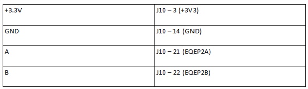
You’ll use the Hercules eQEP peripheral (the quadrature encoder) with the scroll wheel. EQEP module No. 2 is close to the pins you’re already using for the ePWM output. So connect your scroll wheel to that, as shown in Table 1 and Figure 5.
|
 Figure 5 Position of the Encoder
Signals
Figure 5 Position of the Encoder
SignalsWhen you’ve wired up the encoder, you can go to HALCoGen and adapt your firmware.
Integrate the Scroll Wheel in the Firmware
All hardware is connected at this point. But you still have to build in the scroll-wheel functionality. In the Hercules world, you have to do two things: configure the eQEP module in HALCoGen, and adapt your program in Code Composer Studio™ software.
Integrate Encoder Functionality in Firmware
Enable the eQEP driver and configure eQEP module No. 2 (Figure 6 and Figure 7). The HALCoGen settings may seem magical, but my element14 blog explains them.
 Figure 6 Enable Encoder Module 2
 Figure 7 Configure Encoder 2
Initialize the driver in Code Composer Studio software. In your state machine, you’ll poll the wheel’s value at regular times and react on changes. Decrease or increase the PWM signal’s duty cycle depending on the rotary encoder’s status. Refer to the rotary.c, pwm.c and HL_sys_main.c files to see how all of this ties together.
While(1)
{
uRotary = getRotaryPosition();
if (uRotary != uRotaryLastVal) {
uRotaryLastVal = uRotary;
setPwmDutyCycle(uRotary);
}
}
The code for the scroll wheel isn’t difficult either. In this design, you don’t want the encoder to wrap beyond maximum or minimum. You can check rotary.c to see how I’ve coded it. It works, but I’m not fully satisfied with my design to handle the decoding. Feel free to chime in and build a better implementation.
IMPORTANT NOTICE AND DISCLAIMER
TI PROVIDES TECHNICAL AND RELIABILITY DATA (INCLUDING DATASHEETS), DESIGN RESOURCES (INCLUDING REFERENCE DESIGNS), APPLICATION OR OTHER DESIGN ADVICE, WEB TOOLS, SAFETY INFORMATION, AND OTHER RESOURCES “AS IS” AND WITH ALL FAULTS, AND DISCLAIMS ALL WARRANTIES, EXPRESS AND IMPLIED, INCLUDING WITHOUT LIMITATION ANY IMPLIED WARRANTIES OF MERCHANTABILITY, FITNESS FOR A PARTICULAR PURPOSE OR NON-INFRINGEMENT OF THIRD PARTY INTELLECTUAL PROPERTY RIGHTS.
These resources are intended for skilled developers designing with TI products. You are solely responsible for (1) selecting the appropriate TI products for your application, (2) designing, validating and testing your application, and (3) ensuring your application meets applicable standards, and any other safety, security, or other requirements. These resources are subject to change without notice. TI grants you permission to use these resources only for development of an application that uses the TI products described in the resource. Other reproduction and display of these resources is prohibited. No license is granted to any other TI intellectual property right or to any third party intellectual property right. TI disclaims responsibility for, and you will fully indemnify TI and its representatives against, any claims, damages, costs, losses, and liabilities arising out of your use of these resources.
TI’s products are provided subject to TI’s Terms of Sale (www.ti.com/legal/termsofsale.html) or other applicable terms available either on ti.com or provided in conjunction with such TI products. TI’s provision of these resources does not expand or otherwise alter TI’s applicable warranties or warranty disclaimers for TI products.
Mailing Address: Texas Instruments, Post Office Box 655303, Dallas, Texas 75265
Copyright © 2023, Texas Instruments Incorporated
