-
Advancements in mmWave Technology: Launch on Package for Automotive Radars
- 1
- Abstract
- 1Importance of mmWave and LoP in Automotive Radars
- 2Evolution From Non-LoP With Microstrip Patch Antenna to LoP With 3D Antennas
- 3Introduction to TI Launch on Package (LOP)
- 4LOP Design and Operation at 77GHz
- 5Advantages of LoP for mmWave Radar Chips
- 6Applications in Front and Corner Radars
- 7Challenges and Future Developments
- 8Conclusion
- IMPORTANT NOTICE
Advancements in mmWave Technology: Launch on Package for Automotive Radars
Abstract
The landscape of automotive radar technology has undergone significant transformation, particularly in the realm of millimeter-wave (mmWave) semiconductor package technology and 3D waveguide antenna. From the initial use of microstrip patch antennas to the evolution towards 3D antennas, the quest for improved performance and efficiency has been relentless. TI’s Launch on Package (LoP) technology enables direct signal transmission from the package radiating element to the 3D antenna through the waveguide within the PCB, thereby enabling efficient electromagnetic signal transfer. In the current era, the spotlight is on LoP technologies, accompanied by sophisticated 3D waveguide antennas for providing better range and object detection.
1 Importance of mmWave and LoP in Automotive Radars
The utilization of mmWave frequencies, specifically around 77GHz, has become pivotal in enhancing the capabilities of automotive radar systems. This frequency range offers the best resolution and accuracy that are crucial for applications like collision avoidance, adaptive cruise control, blind-spot detection, and cross-traffic alerts. The ability to operate effectively in adverse weather conditions such as rain or fog further solidifies the importance of mmWave in modern automotive radar technology.
2 Evolution From Non-LoP With Microstrip Patch Antenna to LoP With 3D Antennas
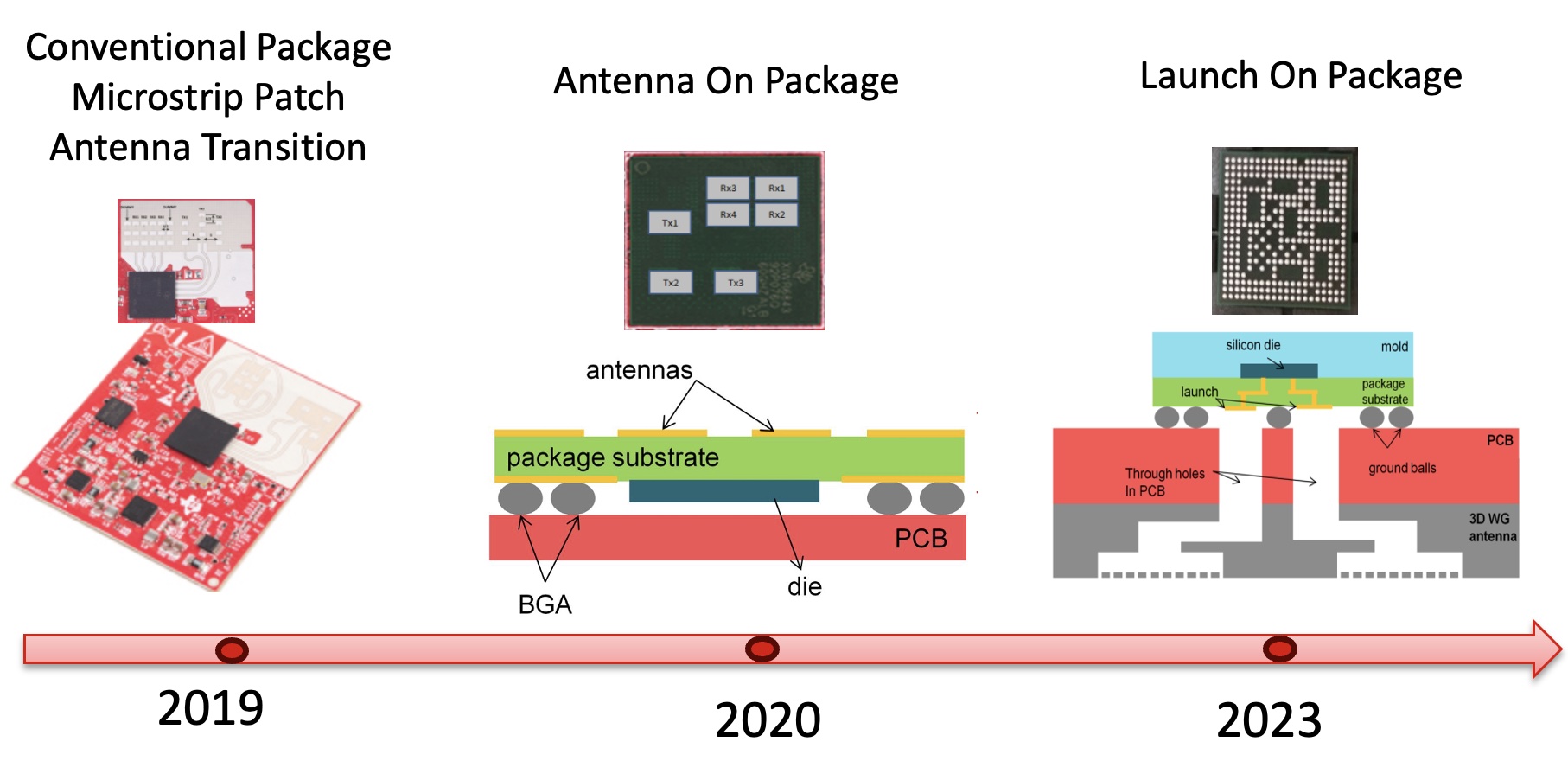
The journey from standard packages with microstrip patch antennas to an advanced LoP package with 3D waveguide antennas was propelled by the need for increased performance and adaptability. Microstrip patch antennas, while effective, had limitations in beamforming and directionality. The transition to 3D antennas marked a significant leap, providing improved capabilities in steering the radar beam with enhanced precision, (see Figure 2-1).
 Figure 2-1 Innovations in mmWave Packages
at Texas Instruments
Figure 2-1 Innovations in mmWave Packages
at Texas InstrumentsTexas Instruments has been innovating mmWave radar package technologies for several years. Early generations of TI mmWave radar integrated circuits used to route the signal from the FCCSP package (non-LoP) through BGA balls, where the signals had to go through four radio frequency (RF) transitions from DIE to package substrate to BGA to PCB before being fed to either a microstrip patch antenna or a 3D waveguide antenna. In later generations where the size of the mmWave radar designs became a key consideration, like in applications such as radar door handles for obstacle detections, TI innovated antenna on package (AoP) technology where antenna elements are integrated within the package. Current generations of TI products include LoP technology where a new way of connecting RF signals to 3D antennas was invented. This connection takes only two RF transitions from DIE to package substrate to waveguide launch which can be directly fed to a 3D antenna through the PCB waveguide. These improvements provide less signal loss and better overall SNR.
| Parameters |
Standard Package (Non-LOP) |
Launch On Package | |
|---|---|---|---|
| Microstrip Patch Antenna | 3D Antenna | 3D Antenna | |
| RF Transitions | 4 (DIE > Package Substrate > (1)BGA > (1)PCB > Microstrip Patch Antenna) | 4 (DIE > Package Substrate > (1)BGA > (1)PCB > Waveguide Launch > 3D Antenna) | 2 (DIE > Package Substrate > Waveguide Launch > 3D Antenna) |
| SNR Performance | Baseline | Baseline | Baseline + (about 1 + dB) |