SNVS536F October 2007 – July 2015 LM2757
PRODUCTION DATA.
- 1 Features
- 2 Applications
- 3 Description
- 4 Revision History
- 5 Device Options
- 6 Pin Configuration and Functions
- 7 Specifications
- 8 Detailed Description
- 9 Application and Implementation
- 10Power Supply Recommendations
- 11Layout
- 12Device and Documentation Support
- 13Mechanical, Packaging, and Orderable Information
1 Features
- Dual Gain Converter (2×, 3/2×) With up to 93% Efficiency
- Inductorless Solution Uses Only 4 Small Ceramic Capacitors
- Total Solution Area < 12 mm2
- True Input-Output and Output-Input Disconnect
- Up to 180-mA Output Current Capability (5 V)
- Selectable 4.1-V, 4.5-V or 5-V Output
- Pre-Regulation Minimizes Input Current Ripple
- 1.24-MHz Switching Frequency for Low-Noise, Low-Ripple Output Voltage
- Integrated Overcurrent and Thermal Shutdown Protection
2 Applications
- USB/USB-OTG/HDMI Power
- Supercapacitor Charger
- Keypad LED Drive
- Audio Amplifier Power Supply
- Low-Current Camera Flash
- General Purpose Li-Ion-to-5-V Conversion
- Cellular Phone SIM Cards
3 Description
The LM2757 is a constant-frequency pre-regulated switched-capacitor charge pump that operates at
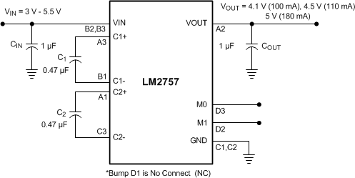
1.25 MHz to produce a low-noise regulated output voltage. The device can be configured to provide up to 100 mA at 4.1 V, 110 mA at 4.5 V, or 180 mA at 5 V. Excellent efficiency is achieved without the use of an inductor by operating the charge pump in a gain of either 3/2 or 2 according to the input voltage and output voltage option selection.
The LM2757 presents a high impedance at the VOUT pin when shut down. This allows for use in applications that require the regulated output bus to be driven by another supply while the LM2757 is shut down.
The LM2757 device comes in a tiny 12-pin 0.4-mm pitch DSBGA package. A perfect fit for space-constrained, battery-operated applications, the device requires only 4 small, inexpensive ceramic capacitors. Built-in soft-start, overcurrent protection, and thermal shutdown features are also included in this device.
Device Information(1)
| PART NUMBER | PACKAGE | BODY SIZE (MAX) |
|---|---|---|
| LM2757 | DSBGA (12) | 1.641 mm × 1.581 mm |
- For all available packages, see the orderable addendum at the end of the data sheet.
Typical Application
