-
REF61xx 高精度電圧リファレンス、内蔵ADCドライブ・バッファ付
REF61xx 高精度電圧リファレンス、内蔵ADCドライブ・バッファ付
1 特長
- 優れた温度ドリフト係数性能
- -40℃~+125℃の範囲で8ppm/℃ (最大値)
- 非常に低ノイズ
- 総ノイズ: 47µFコンデンサで5µVRMS
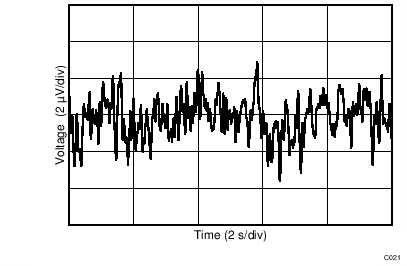
- 1/fノイズ(0.1Hz~10Hz): 3µVPP/V
- ADCドライブ・バッファ内蔵
- 低い出力インピーダンス: 50mΩ未満(0~200kHz)
- ADS8881との組み合わせで最初のサンプルでも18ビットの精度
- バースト・モードのDAQシステムに対応
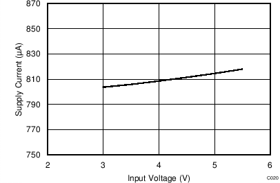
- 低い消費電流: 820μA
- 低いシャットダウン時電流: 1µA
- 高い初期精度: ±0.05%
- 非常に低いノイズと歪み
- 出力電流ドライブ: ±4mA
- 短絡電流をプログラム可能
- ADS88xxファミリのSAR ADCおよびADS127xxファミリの広帯域ΔΣ ADCのREFピンを駆動できることを確認済み
2 アプリケーション
- ATEテスターおよびオシロスコープ
- テストおよび計測機器
- PLC用のアナログ入力モジュール
- 医療用機器
- 高精度データ・アクイジション・システム
3 概要
REF6000ファミリの電圧リファレンスには、低出力インピーダンスのバッファが搭載されているため、ユーザーは高精度データ・コンバータのREFピンを直接駆動しながら、直線性、歪み、ノイズ性能を維持できます。ほとんどの高精度SARおよびデルタ-シグマADCでは、変換プロセス中に、バイナリ重み付けされたコンデンサをREFピン上に切り替えます。この動的な負荷をサポートするため、電圧リファレンスの出力は、低い出力インピーダンス(高い帯域幅)のバッファを経由する必要があります。REF6000ファミリのデバイスは、ADS88xxファミリのSAR ADC、ADS127xxファミリのデルタ-シグマADC、および他のD/Aコンバータ(DAC)のREFピンを駆動するのに最適ですが、他の用途にも使用できます。
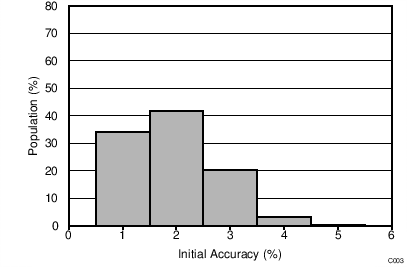
REF6000ファミリの電圧リファレンスは、ADS8881のREFピンを駆動中の最初の変換時でも出力電圧が1 LSB (18ビット)以上低下しません。この機能は、バースト・モード、イベント・トリガ、等価時間サンプリング、可変サンプリング・レートのデータ・アクイジション・システムに非常に便利です。REF6000ファミリのREF61xxバリエーションは、最大温度ドリフト係数の定格がわずか8 ppm/℃で、電圧リファレンスと低インピーダンスの出力バッファの両方の組み合わせについて、初期精度が0.05%です。REF6000ファミリの各種の温度ドリフト係数オプションについては、デバイス比較表を参照してください。
製品情報(1)
| 型番 | パッケージ | 本体サイズ(公称) |
|---|---|---|
| REF61xx | VSSOP (8) | 3.00mm×3.00mm |
- 提供されているすべてのパッケージについては、データシートの末尾にあるパッケージ・オプションについての付録を参照してください。
代表的なアプリケーション
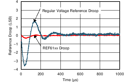
リファレンス電圧低下の比較
(1 LSB = 19.07µV、ADS8881で1 MSPSの場合)
4 改訂履歴
Changes from A Revision (June 2016) to B Revision
- 「概要」を変更Go
- Changed the Device Comparison Table Go
- Changed list of devices for output current in Recommended Operating Conditions Go
- Changed load regulation max value for REF6150 at TA = –40°C to +125°C from 30 to 50 Go
- Changed Figure 1Go
- Changed Figure 2Go
- Changed Figure 5Go
- Changed "second pass" to "final pass" in last paragraph of Solder Heat Shift section Go
- Added link to SLYY097 in Overview sectionGo
Changes from * Revision (May 2016) to A Revision
- 製品プレビューから生産データへ変更Go
6 Pin Configuration and Functions
Pin Functions
| PIN | TYPE | DESCRIPTION | |
|---|---|---|---|
| NAME | NO. | ||
| EN | 2 | Input | Enable pin |
| FILT | 4 | — | Filter capacitor pin. A capacitor (CFILT) ≥ 1 µF must be connected between the FILT pin and ground for stability. |
| GND_F | 7 | Ground | Ground force pin |
| GND_S | 8 | Ground | Ground sense pin |
| OUT_F | 6 | Output | Output voltage force pin |
| OUT_S | 5 | Input | Output voltage sense pin |
| SS | 3 | — | Short circuit current limit pin. Connect a resistor to this pin to set the output short-circuit current limit. Connect to VIN pin for highest current limit |
| VIN | 1 | Power | Input supply voltage pin |
7 Specifications
7.1 Absolute Maximum Ratings(1)
over operating free-air temperature range (unless otherwise noted)| MIN | MAX | UNIT | ||
|---|---|---|---|---|
| Input voltage | VIN | –0.3 | 6 | V |
| VEN | –0.3 | VIN + 0.3 | V | |
| Operating temperature, TA | –55 | 150 | °C | |
| Junction temperature, Tj | 150 | °C | ||
| Storage temperature, Tstg | –65 | 150 | °C | |
7.2 ESD Ratings
| VALUE | UNIT | |||
|---|---|---|---|---|
| V(ESD) | Electrostatic discharge | Human-body model (HBM), per ANSI/ESDA/JEDEC JS-001(1) | ±1000 | V |
| Charged-device model (CDM), per JEDEC specification JESD22-C101(2) | ±250 | |||
7.3 Recommended Operating Conditions
7.4 Thermal Information
| THERMAL METRIC(1) | REF61xx | UNIT | |
|---|---|---|---|
| DGK (VSSOP) | |||
| 8 PINS | |||
| RθJA | Junction-to-ambient thermal resistance | 158.5 | °C/W |
| RθJC(top) | Junction-to-case (top) thermal resistance | 51.2 | °C/W |
| RθJB | Junction-to-board thermal resistance | 79.5 | °C/W |
| ψJT | Junction-to-top characterization parameter | 5.2 | °C/W |
| ψJB | Junction-to-board characterization parameter | 78.0 | °C/W |
| RθJC(bot) | Junction-to-case (bottom) thermal resistance | N/A | °C/W |
7.5 Electrical Characteristics
at TA = 25°C, VIN = 5 V for all devices except REF6150, VIN = 5.4 V for REF6150, IL = 0 mA, CL = 22 µF, CFILT = 1 µF, and VEN = 5 V (unless otherwise noted)| PARAMETER | TEST CONDITIONS | MIN | TYP | MAX | UNIT | |||||
|---|---|---|---|---|---|---|---|---|---|---|
| ACCURACY AND DRIFT | ||||||||||
| Output voltage accuracy | -0.05% | 0.05% | ||||||||
| Output voltage temperature coefficient(1) | 8 | ppm/°C | ||||||||
| LINE AND LOAD REGULATION | ||||||||||
| ΔVO(ΔVI) | Line regulation | REF6125 | VOUT + 0.5 V ≤ VIN ≤ 5.5 V | TA = 25°C | 4 | 20 | ppm/V | |||
| TA = –40°C to +125°C | 30 | |||||||||
| REF6130, REF6133, REF6141, REF6145 | VOUT + 0.25 V ≤ VIN ≤ 5.5 V | TA = 25°C | 4 | 20 | ||||||
| TA = –40°C to +125°C | 30 | |||||||||
| REF6150 | VOUT + 0.3 V ≤ VIN ≤ 5.5 V | TA = 25°C | 7 | 60 | ||||||
| TA = –40°C to +125°C | 120 | |||||||||
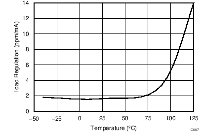
| ΔVO(ΔIL) | Load regulation, sourcing and sinking | REF6125, REF6130, REF6133, REF6141 | IL = 0 mA to 4 mA, VIN = VOUT + 600 mV |
TA = 25°C | 2 | 20 | ppm/mA | |||
| TA = –40°C to +125°C | 30 | |||||||||
| REF6145 | IL = 0 mA to 3.5 mA, VIN = VOUT + 600 mV |
TA = 25°C | 2 | 20 | ||||||
| TA = –40°C to +125°C | 30 | |||||||||
| REF6150 | IL = 0 mA to 3 mA, VIN = VOUT + 400 mV |
TA = 25°C | 2 | 20 | ||||||
| TA = –40°C to +125°C | 50 | |||||||||
| ISC | Short-circuit current | SS = open | 10.5 | mA | ||||||
| NOISE | ||||||||||
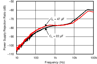
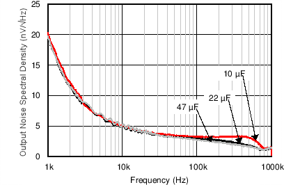
| Total integrated noise | CL = 22 µF | 5 | µVRMS | |||||||
| CL = 47 µF | 5 | |||||||||
| Low frequency noise | 0.1 Hz ≤ f ≤ 10 Hz | 3 | µVPP/V | |||||||
| OUTPUT IMPEDANCE | ||||||||||
| Output impedance | f = DC to 200 kHz, CL= 47 μF | 50 | mΩ | |||||||
| TURN-ON TIME | ||||||||||
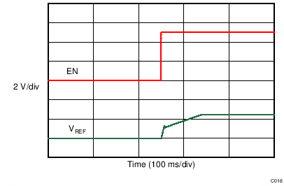
| ton | Turn-on time | 0.1% settling, CL = 47 µF, SS = open, REF6125 | 100 | ms | ||||||
| HYSTERESIS AND LONG TERM DRIFT | ||||||||||
| Long term stability | 0 to 1000h at 25°C | 80 | ppm | |||||||
| 1000h to 2000h at 25°C | 20 | |||||||||
| Output voltage hysteresis(2) | 25°C, –40°C,125°C, 25°C (cycle 1) | 33 | ppm | |||||||
| 25°C, –40°C,125°C, 25°C (cycle 2) | 8 | |||||||||
| CAPACITIVE LOAD | ||||||||||
| CL | Stable output capacitor value | 10 | 47 | µF | ||||||
| OUTPUT VOLTAGE | ||||||||||
| VOUT | Output voltage | REF6125 | 2.5 | V | ||||||
| REF6130 | 3 | |||||||||
| REF6133 | 3.3 | |||||||||
| REF6141 | 4.096 | |||||||||
| REF6145 | 4.5 | |||||||||
| REF6150 | 5 | |||||||||
| POWER SUPPLY | ||||||||||
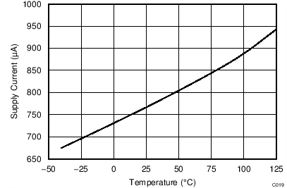
| ICC | Supply current | REF6125, REF6130, REF6133, REF6141 | Active mode, VEN = 5 V | TA = 25°C | 0.82 | 0.90 | mA | |||
| TA = –40°C to +125°C | 1.1 | |||||||||
| REF6145, REF6150 | Active mode, VEN = 5 V | TA = 25°C | 0.83 | 0.95 | ||||||
| TA = –40°C to +125°C | 1.15 | |||||||||
| Shutdown mode, VEN = 0 V | TA = 25°C | 1 | 3 | µA | ||||||
| TA = –40°C to +125°C | 15 | |||||||||
| Enable pin voltage | Voltage reference in active mode (EN = 1) | 1.6 | V | |||||||
| Voltage reference in shutdown mode (EN = 0) | 0.6 | |||||||||
| Enable pin current | VEN = 5 V | 100 | 150 | nA | ||||||
| Dropout voltage | REF6125 | IL = 0 mA | 500 | 500 | mV | |||||
| IL = 4 mA | 600 | |||||||||
| REF6130, REF6133, REF6141 | IL = 0 mA | 50 | 250 | |||||||
| IL = 4 mA | 600 | |||||||||
| REF6145 | IL = 0 mA | 50 | 250 | |||||||
| IL = 3.5 mA | 600 | |||||||||
| REF6150 | IL = 0 mA | 100 | 300 | |||||||
| IL = 3 mA | 400 | |||||||||
7.6 Typical Characteristics
at TA = 25°C, IL = 0 mA, and VIN = 5 V, using REF6125 (unless otherwise noted)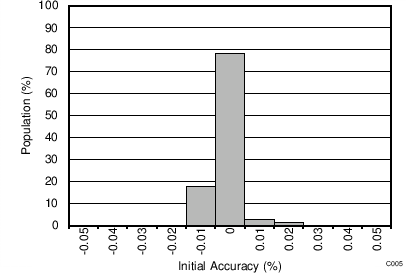
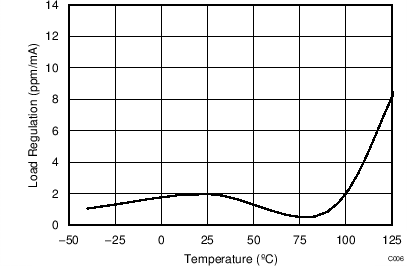
| VIN = VOUT + 600 mV, | ||
| IL = 0 mA to 4 mA | ||
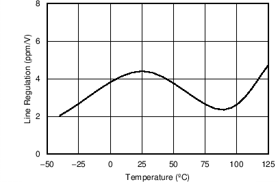
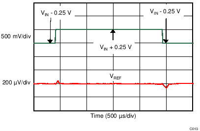
| VOUT + 0.25 V ≤ VIN ≤ 5.5 V | ||
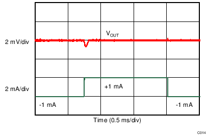
| Load current = ±1 mA |
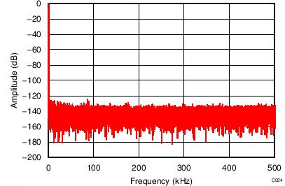
| REF6150 driving REF pin of ADS8881, | ||
| fIN = 1 kHz, SNR = 100.5 dB, THD = –125.9 dB |
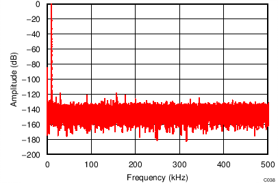
| REF6150 driving REF pin of ADS8881, | ||
| fIN = 10 kHz, SNR = 99.2 dB, THD = –119.4 dB |
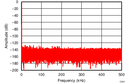
| REF6141 driving REF pin of ADS8881, | ||
| fIN = 2 kHz, SNR = 99 dB, THD = –123.6 dB |
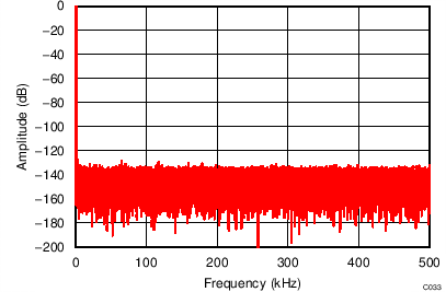
| REF6125 driving REF pin of ADS8881, | ||
| fIN = 1 kHz, SNR = 95.4 dB, THD = –124 dB |
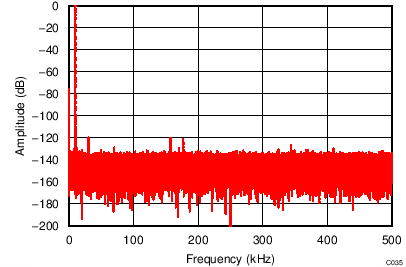
| REF6125 driving REF pin of ADS8881, | ||
| fIN = 10 kHz, SNR = 94.0 dB, THD = –119.3 dB |
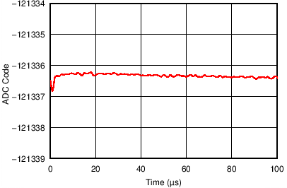
| REF6150 driving REF pin of ADS8881 operating at 1 MSPS, | ||
| negative full-scale input to ADS8881 |
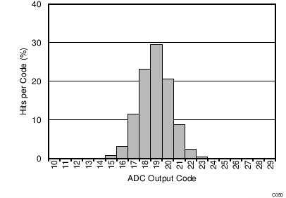
| AINP = AINN = VREF / 2 for ADS8881, | ||
| sampling rate = 1 MSPS |
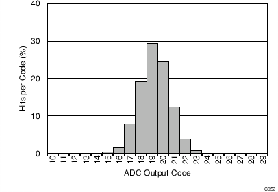
| AINP = AINN = VREF / 2 for ADS8881, | ||
| sampling rate = 100 kSPS |

| 1 LSB = 19.07 µV, with ADS8881 at 1 MSPS |
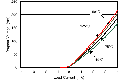
| VIN = VOUT + 600 mV, | ||
| IL = 0 mA to 4 mA | ||
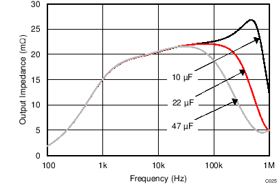
| Graph obtained by design simulation |
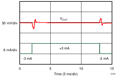
| Load current = ±3 mA |
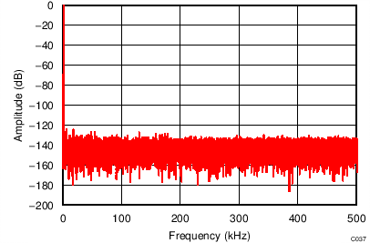
| REF6150 driving REF pin of ADS8881, | ||
| fIN = 2 kHz, SNR = 100.4 dB, THD = –123.9 dB |
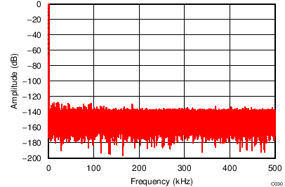
| REF6141 driving REF pin of ADS8881, | ||
| fIN = 1 kHz, SNR = 99 dB, THD = –124.4 dB |
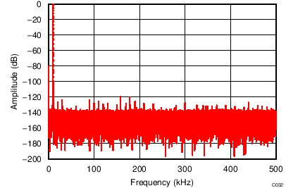
| REF6141 driving REF pin of ADS8881, | ||
| fIN = 10 kHz, SNR = 97.2 dB, THD = –119.7 dB |
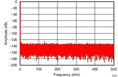
| REF6125 driving REF pin of ADS8881, | ||
| fIN = 2 kHz, SNR = 95.4 dB, THD = –123.5 dB |
| REF6150 driving REF pin of ADS8881 operating at 1 MSPS, | ||
| positive full-scale input to ADS8881 |
| REF6150 driving REF pin of ADS8881 operating at 1 MSPS, | ||
| AINP = AINN = VREF / 2 for ADS8881 |
| AINP = AINN = VREF / 2 for ADS8881, | ||
| sampling rate = 500 kSPS |
| AINP = AINN = VREF / 2 for ADS8881, | ||
| sampling rate = 20 kSPS |
8 Parameter Measurement Information
8.1 Solder Heat Shift
The materials used in the manufacture of the REF61xx have differing coefficients of thermal expansion, and result in stress on the device die when the part is heated. Mechanical and thermal stress on the device die sometimes causes the output voltages to shift, degrading the initial accuracy specifications of the product. Reflow soldering is a common cause of this error.
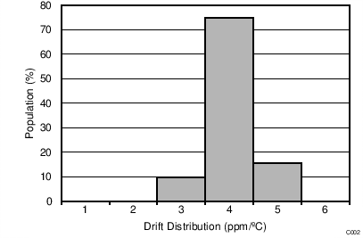
In order to illustrate this effect, a total of 128 devices were soldered on eight printed circuit boards (PCBs), with 16 devices on each PCB, using lead-free solder paste, and the manufacturer-suggested reflow profile. The reflow profile is as shown in Figure 40. The printed circuit board is comprised of FR4 material. The board thickness is 1.65 mm and the area is 101.6 mm × 127 mm.
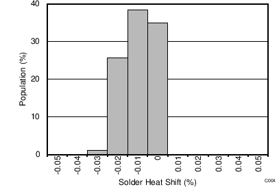
The reference output voltage is measured before and after the reflow process; the typical shift is displayed in Figure 41. Although all tested units exhibit very low shifts (< 0.03%), higher shifts are also possible depending on the size, thickness, and material of the PCB.
The histogram displays the typical shift for exposure to a single reflow profile. Exposure to multiple reflows, as is common on PCBs with surface-mount components on both sides, causes additional shifts in the output bias voltage. If the PCB is exposed to multiple reflows, solder the device in the final pass to minimize exposure to thermal stress.
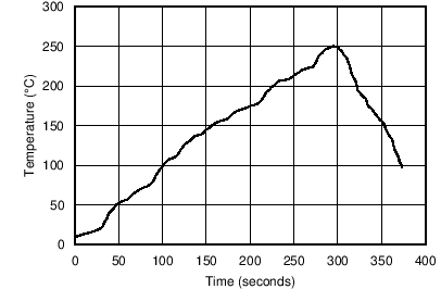 Figure 40. Reflow Profile
 Figure 41. Solder Heat Shift Distribution
8.2 Thermal Hysteresis
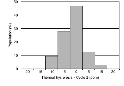
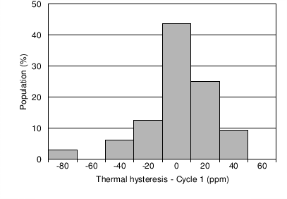
Thermal hysteresis for the device is defined as the change in output voltage after operating the device at 25°C, cycling the device through the specified temperature range, and returning to 25°C. Thermal hysteresis was measured with the REF61xx soldered to a PCB, similar to a real-world application. The PCB was baked at 150°C for 30 minutes before thermal hysteresis was measured. Thermal hysteresis is expressed as:

where
- VHYST = thermal hysteresis (in units of ppm).
- VNOM = the specified output voltage.
- VPRE = output voltage measured at 25°C pretemperature cycling.
- VPOST = output voltage measured after the device has cycled from 25°C through the specified temperature range of –40°C to 125°C and returns to 25°C.
Typical thermal hysteresis distribution is shown in Figure 42 and Figure 43.
 Figure 42. Thermal Hysteresis Distribution (Cycle 1)
 Figure 43. Thermal Hysteresis Distribution (Cycle 2)
8.3 Reference Droop Measurements
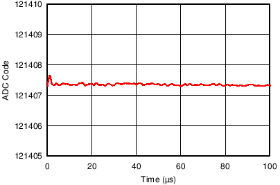
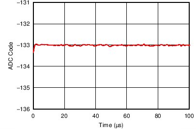
Many applications, such as event-triggered and multiplexed data-acquisition systems, require the very first conversion of the ADC to have 18-bit or greater precision. These types of data-acquisition systems capture data in bursts, and are also called burst-mode, data-acquisition systems. Achieving 18-bit precision for the first sample is a very difficult using a conventional voltage reference because the voltage reference droop limits the accuracy of the first few conversions. The REF61xx have an integrated ADC drive buffer that makes sure the reference droop is less than 1 LSB at 18-bit precision when used with the ADS8881, even at full throughput. Figure 44 and Figure 45 show the REF61xx output voltage droop when driving the REF pin of the ADS8881 at positive and negative full-scale inputs, respectively.

| REF6150 driving REF pin of ADS8881 operating at 1 MSPS, | ||
| positive full-scale input to ADS8881 |

| REF6150 driving REF pin of ADS8881 operating at 1 MSPS, | ||
| negative full-scale input to ADS8881 |
Direct measurement of the reference droop to 18-bit accuracy can be a challenging process. Therefore, the plots in Figure 44 and Figure 45 were obtained by processing the output code of the ADC. The ADC output code is given by:
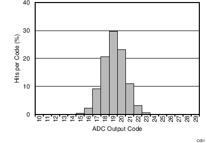
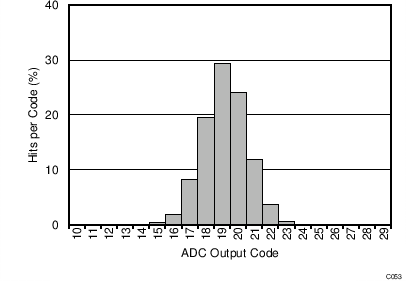
If the input voltage is kept constant, VREF is computed by monitoring the ADC output code C. The ADC code usually has six to seven LSBs of code spread due to the inherent noise of the ADC. In order to measure reference droop, this noise must be reduced drastically. Noise reduction is done by averaging the output code multiple times, as described in the next paragraph.
Figure 46 shows the setup that was used to measure the reference droop. The output ADC code was captured using a field-programmable gate array (FPGA), and post-processing was done on a personal computer. The input to the THS4521, and hence in turn to the ADS8881, is a constant dc voltage (close to positive or negative full-scale because this condition is the worst-case for charge drawn from the REF pin). The dc source must have extremely low noise. After the REF61xx device is powered up and stable, the FPGA sends commands to the ADS8881 to capture data in bursts. The ADS8881 is initially in idle mode for 100 ms. The FPGA then sends a command to the ADS8881 to perform 100 conversions at 1 MSPS. The ADC code corresponding to these 100 conversions (one burst of data) is stored as the first row in a 1000 × 100 dimensional array. This operation is repeated 1000 times, and the data corresponding to each burst is stored in a new row of the 1000 × 100 dimensional array. Finally, each column in this array is averaged to get a final data-set of 100 elements. This final data-set now has code spread that is much less than 1 LSB because most of the noise has now been removed through averaging. This data-set was plotted on a graph with X axis = column number (each column number corresponds to 1 µs of time because the sampling rate is 1 MSPS), and Y axis = ADC output code to obtain reference-droop measurements.
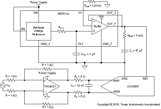 Figure 46. Burst-Mode Measurement Setup
8.4 1/f Noise Performance
Typical 0.1-Hz to 10-Hz voltage noise for the REF6125 is shown in Figure 47. The 1/f noise scales with output voltage, but remains 3 µVPP/V for all the variants. Peak-to-peak noise measurement setup is shown in Figure 48.
 Figure 47. 0.1-Hz to 10-Hz Noise
 Figure 48. 0.1-Hz to 10-Hz Noise Measurement Setup
9 Detailed Description
9.1 Overview
Most SAR ADCs, and a few delta-sigma ADCs, switch binary-weighted capacitors onto the REF pin during the conversion process. The magnitude of the capacitance switched onto the REF pin during each conversion depends on the input signal to the ADC. If a voltage reference is directly connected to the REF pin of these ADCs, the reference voltage droops because of the dynamic input signal dependent load of the binary-weighted capacitors. Because the reference voltage droop now has input signal dependance, significant degradation in THD and linearity for the system occurs.
In order to support this dynamic load and preserve the ADC linearity, distortion and noise performance, the output of the voltage reference must be buffered with a low-output impedance (high-bandwidth) buffer. The REF61xx family of voltage references have an integrated low output impedance buffer that enables the user to directly drive the REF pin of a SAR ADC, while preserving ADC linearity and distortion. In addition, the total noise in the full bandwidth of the REF61xx is extremely low, thus preserving the noise performance of the ADC. Voltage-Reference Impact on Total Harmonic Distortion (SLYY097) correlates the effect of reference settling to ADC distortion, and how the REF61xx achieves lowest distortion with minimal components and lowest power consumption.
The output voltage of the REF61xx does not droop below 1 LSB (18-bit), even during the first conversion while driving the REF pin of the ADS8881. This feature is useful in burst-mode, event-triggered, equivalent-time sampling, and variable-sampling-rate data-acquisition systems. Functional Block Diagram shows a simplified schematic of the REF61xx.
9.2 Functional Block Diagram
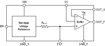
9.3 Feature Description
9.3.1 Integrated ADC Drive Buffer
Many ADC data sheets specify a few microamps of average current draw from the REF pin. Almost all voltage references provide these few microamps of average current; but not all voltage references are practical for driving a high-resolution, high-throughput SAR ADC because the peak current drawn can be very high when the capacitors are switched on the REF pin. The worst-case demand for the voltage reference is during a burst-mode conversion, when the ADC is idle for a very long time, before a conversion is initiated, and the first sample converted is expected to be precise. Usually, a large capacitor is connected between the REF pin and ground pin (or sometimes between the REFP and REFM pins) of the ADC to smoothen the current load and reduce the burden on the voltage reference. The voltage reference must then be capable of providing the average current required to completely charge the reference capacitor, but without causing the reference voltage to droop significantly. Most voltage references lack the ability to completely charge the reference capacitor, and settle when the binary-weighted capacitors are being switched onto the REF pin because of the large output impedance. Usually, voltage references have output impedances in the range of 10's of ohms at frequencies higher than 100 Hz. The output voltage of the voltage reference must be buffered with a low output impedance (usually high bandwidth) amplifier to achieve excellent linearity and distortion performance.
The key amplifier specifications to be considered when designing a reference buffer for a high-precision ADC are: low offset, low drift, wide bandwidth, and low output impedance. While it is possible to select an amplifier that sufficiently meets all these requirements, the amplifier comes at a cost of excessive power consumption. For example, the OPA350 is a 38-MHz bandwidth amplifier with a maximum offset of 0.5 mV, and low offset drift of 4 µV/ºC, but consumes a quiescent current of 5.2mA. This is because (from an amplifier design perspective) offset and drift are dc specifications, whereas bandwidth, low output impedance, and high capacitive drive capability are high-frequency specifications. Therefore, achieving all the performance in one amplifier requires power. However, a more efficient design to meet the low power budget is to use a composite reference buffer, which uses an amplifier with superior high-frequency specifications in the feedback loop of a dc precision amplifier to get the overall performance at much lower power consumption. Figure 49 shows such a composite amplifier design with the OPA333 (dc precision amplifier) and THS4281 (high-bandwidth amplifier). This reference buffer design requires three devices, and a large number of external components. This solution still consumes close to 2 mA of quiescent current.
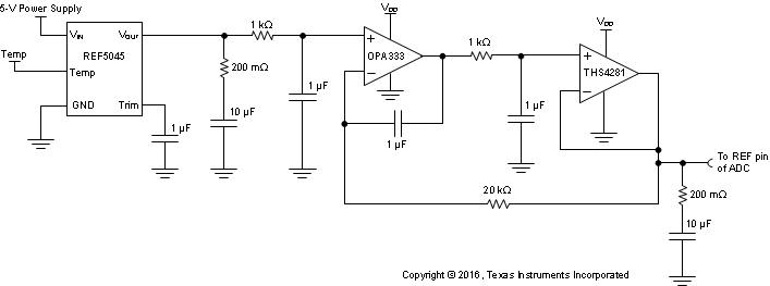 Figure 49. Composite Amplifier Reference Buffer
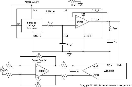
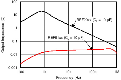
The REF61xx family of voltage references have an integrated low output impedance buffer (ADC drive buffer); therefore, there is no need for an external buffer while driving the REF pin of high-precision, high-throughput SAR ADCs, as shown in Figure 50. The ADC drive buffer of the REF61xx is capable of replenishing a charge of 70 pC on a 47-µF capacitor in 1 µs, without allowing the voltage on the capacitor to droop more than 1 LSB at 18-bit precision. The REF61xx are trimmed at multiple temperatures in production, achieving a max drift of just 8 ppm/°C for both the voltage reference and the buffer combined, while operating at a typical quiescent current of 820 µA. Figure 51 compares the output impedance of a regular voltage reference (REF20xx) and a voltage reference with integrated ADC drive buffer (REF61xx). Figure 52 compares the burst-mode, reference-settling performance of a regular voltage reference and the REF61xx.
 Figure 50. REF61xx Driving REF Pin of ADS8881 SAR ADC


| 1 LSB = 19.07 µV, with ADS8881 at 1 MSPS |
9.3.2 Temperature Drift
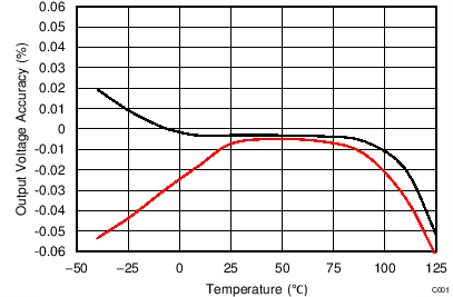
The REF61xx family is designed for minimal drift error, defined as the change in output voltage over temperature. The drift is calculated using the box method, as described by the following equation:

9.3.3 Load Current
The REF6125, REF6130, REF6133 and REF6141 are specified to deliver current load of ±4 mA. The REF6145 is specified to deliver ±3.5 mA, and the REF6150 is specified to deliver ±3 mA. The REF61xx are protected from short circuits at the output by limiting the output short-circuit current.
The short-circuit current limit (ISC) of the REF61xx family of devices is adjusted by connecting a resistor (RSS) on the SS pin. The short-circuit current limit when the REF61xx device is sourcing current can be calculated as shown in Equation 4:

The short circuit current limit when the REF61xx device is sinking is calculated as shown in Equation 5:

The recommended output current of the REF61xx also depends on the resistor connected to the SS pin. The recommended output current (sourcing and sinking) for the REF6125, REF6130, REF6133 and REF6141 is given by Equation 6:

The recommended output current (sourcing and sinking) for the REF6145 is given by Equation 7:

The recommended output current (sourcing and sinking) for the REF6150 is given by Equation 8:

The temperature of the device increases according to Equation 9:

where
- TJ = junction temperature (°C).
- TA = ambient temperature (°C).
- PD = power dissipated (W).
- RθJA = junction-to-ambient thermal resistance (°C/W).
The REF61xx maximum junction temperature must not exceed the absolute maximum rating of 150°C.
9.3.4 Stability
The REF61xx family of voltage references are stable with output capacitor values ranging from 10 µF to 47 µF. At a low output-capacitor value of 10 µF, an effective series resistance (ESR) of 20 mΩ to 100 mΩ is required for stability; whereas, at a higher value of 47 µF, an ESR of 5 mΩ to 100 mΩ is required. The shaded region in Figure 53 shows the stable region of operation for the REF61xx devices.
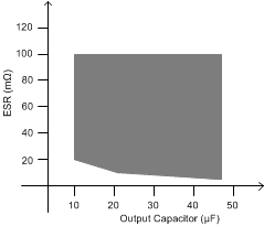 Figure 53. Stable Output Capacitor Range
A capacitor of value 1 µF is required at the FILT pin for stability and noise performance. A low ESR (5 mΩ to 20 mΩ) is easily achieved by increasing the PCB trace length, thus eliminating the need for a discrete resistor. Higher values of ESR (greater than 20 mΩ, but lesser than 100 mΩ) can be intentionally added to increase the output bandwidth of the REF61xx. This higher ESR improves the transient performance of the REF61xx, but worsens noise performance because of increased bandwidth.
9.4 Device Functional Modes
When the EN pin of the REF61xx is pulled high, the device is in active mode. The device must be in active mode for normal operation.
To place the REF61xx into a shutdown mode, pull the ENABLE pin low. When in shutdown mode, the output of the device becomes high impedance and the quiescent current of the device reduces to 1 µA (typ). See the enable pin voltage parameter in the Electrical Characteristics table for logic high and logic low voltage levels.
