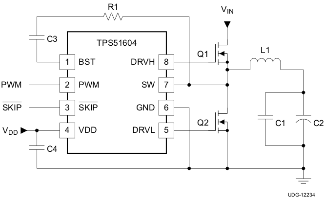
The TPS51604 drivers are optimized for high-frequency CPU VCORE applications. Advanced features such as reduced dead-time drive and auto zero crossing are used to optimize efficiency over the entire load range.
The SKIP pin provides the option of CCM operation to support controlled management of the output voltage. In addition, the TPS51604 supports two low-power modes. With the PWM input in tri-state, quiescent current is reduced to 130 µA, with immediate response. When SKIP is held at tri-state, the current is reduced to 8 µA (typically 20 µs is required to resume switching). Paired with the appropriate TI controller, the drivers deliver an exceptionally high performance power supply system.
The TPS51604 device is packaged in a space saving, thermally-enhanced 8-pin, 2-mm x 2-mm WSON package and operates from –40°C to 105°C.
PART NUMBER | PACKAGE | BODY SIZE (NOM) |
---|---|---|
TPS51604 | WSON (8) | 2.00 mm × 2.00 mm |
Changes from A Revision (August 2013) to B Revision
PIN | I/O(1) | DESCRIPTION | |
---|---|---|---|
NAME | NO. | ||
BST | 1 | I | High-side N-channel FET bootstrap voltage input; power supply for high-side driver |
DRVH | 8 | O | High-side N-channel gate drive output |
DRVL | 5 | O | Synchronous low-side N-channel gate drive output |
GND | 6 | G | Synchronous low-side N-channel gate drive return and device reference |
PWM | 2 | I | PWM input. A tri-state voltage on this pin turns off both the high-side (DRVH) and low-side drivers (DRVL) |
SKIP | 3 | I | When SKIP is LO, the zero crossing comparator is active. The power chain enters discontinuous conduction mode when the inductor current reaches zero. When SKIP is HI, the zero crossing comparator is disabled, and the driver outputs follow the PWM input. A tri-state voltage on SKIP puts the driver into a very-low power state. |
SW | 7 | I/O | High-side N-channel gate drive return. Also, zero-crossing sense input |
VDD | 4 | I | 5-V power supply input; decouple to GND with a ceramic capacitor with a value of 1 µF or greater |
Thermal Pad | G | Tie to system GND plane with multiple vias |
MIN | MAX | UNIT | ||
---|---|---|---|---|
Input voltage | VDD | –0.3 | 6 | V |
PWM, SKIP | –0.3 | 6 | ||
Output voltage | BST | –0.3 | 35 | V |
BST (transient <20 ns) | –0.3 | 38 | ||
BST to SW; DRVH to SW | –0.3 | 6 | ||
SW | –2 | 30 | ||
DRVH, SW (transient <20 ns) | –5 | 38 | ||
DRVL | –0.3 | 6 | ||
Ground pins | GND to PAD | –0.3 | 0.3 | V |
Operating junction temperature, TJ | –40 | 125 | °C | |
Storage temperature range, Tstg | –55 | 150 | °C |
VALUE | UNIT | |||
---|---|---|---|---|
V(ESD) | Electrostatic discharge | Human body model (HBM), per AEC Q100-002(1) | ±2000 | V |
Charged device model (CDM), per AEC Q100-011 | ±750 |
MIN | NOM | MAX | UNIT | ||
---|---|---|---|---|---|
Input voltage | VDD | 4.5 | 5 | 5.5 | V |
PWM, SKIP | –0.1 | 5.5 | |||
Output voltage | BST | –0.1 | 34 | V | |
BST to SW; DRVH to SW | –0.1 | 5.5 | |||
SW | –1 | 28 | |||
DRVL | –0.1 | 5.5 | |||
Ground pins | GND to PAD | –0.1 | 0.1 | V | |
Operating junction temperature, TJ | –40 | 105 | °C |
THERMAL METRIC(1) | TPS51604 | UNIT | |
---|---|---|---|
WSON (DSG) | |||
8 PINS | |||
RθJA | Junction-to-ambient thermal resistance | 63.1 | °C/W |
RθJC(top) | Junction-to-case (top) thermal resistance | 74.1 | °C/W |
RθJB | Junction-to-board thermal resistance | 34.3 | °C/W |
ψJT | Junction-to-top characterization parameter | 2.0 | °C/W |
ψJB | Junction-to-board characterization parameter | 34.9 | °C/W |
RθJC(bot) | Junction-to-case (bottom) thermal resistance | 11.7 | °C/W |
PARAMETER | TEST CONDITIONS | MIN | TYP | MAX | UNIT | |
---|---|---|---|---|---|---|
VDD INPUT SUPPLY | ||||||
ICC | Supply current (operating) | VSKIP = VVDD or VSKIP = 0 V, PWM = High |
160 | 600 | µA | |
VSKIP = VVDD or VSKIP = 0 V, PWM = Low |
250 | |||||
VSKIP = VVDD or VSKIP = 0 V, PWM = Float |
130 | |||||
VSKIP = Float | 8 | |||||
VDD UNDERVOLTAGE LOCKOUT (UVLO) | ||||||
VUVLO | UVLO threshold | Rising threshold | 4.15 | V | ||
Falling threshold | 3.7 | |||||
VUVHYS | UVLO hysteresis | 0.2 | V | |||
PWM AND SKIP I/O SPECIFICATIONS | ||||||
RI | Input impedance | Pullup to VDD | 1.7 | MΩ | ||
Pulldown (to GND) | 800 | kΩ | ||||
VIL | Low-level input voltage | 0.6 | V | |||
VIH | High-level input voltage | 2.65 | V | |||
VIHH | Hysteresis | 0.2 | V | |||
VTS | Tri-state voltage | 1.3 | 2.0 | V | ||
tTHOLD(off1) | Tri-state activation time (falling) PWM | 60 | ns | |||
tTHOLD(off2) | Tri-state activation time (rising) PWM | 60 | ns | |||
tTSKF | Tri-state activation time (falling) SKIP | 1 | µs | |||
tTSKR | Tri-state activation time (rising) SKIP | 1 | µs | |||
t3RD(PWM) | Tri-state exit time PWM | 100 | ns | |||
t3RD(SKIP) | Tri-state exit time SKIP | 50 | µs | |||
HIGH-SIDE GATE DRIVER (DRVH) | ||||||
tR(DRVH) | Rise time | DRVH rising, CDRVH = 3.3 nF; 20% to 80% | 30 | ns | ||
tRPD(DRVH) | Rise time propogation delay | CDRVH = 3.3 nF | 40 | ns | ||
RSRC | Source resistance | Source resistance, (VBST– VSW) = 5 V, high state, (VBST – VDRVH) = 0.1 V |
4 | 8 | Ω | |
tF(DRVH) | Fall time | DRVH falling, CDRVH = 3.3 nF | 8 | ns | ||
tFPD(DRVH) | Fall-time propagation delay | CDRVH = 3.3 nF | 25 | ns | ||
RSNK | Sink resistance | Sink resistance, (VBST – VSW) forced to 5 V, low state (VDRVH – VSW) = 0.1 V |
0.5 | 1.6 | Ω | |
RDRVH | DRVH to SW resistance(1) | 100 | kΩ | |||
LOW-SIDE GATE DRIVER (DRVL) | ||||||
tR(DRVL) | Rise time | DRVL rising, CDRVL = 3.3 nF; 20% to 80% | 15 | ns | ||
tRPD(DRVL) | Rise time propagation delay | CDRVL = 3.3 nF | 35 | ns | ||
RSRC | Source resistance | Source resistance, (VVDD–GND) = 5 V, high state, (VVDD – VDRVL) = 0.1 V |
1.5 | 3 | Ω | |
tF(DRVL) | Fall time | DRVL falling, CDRVL = 3.3 nF | 10 | ns | ||
tFPD(DRVL) | Fall-time propagation delay | CDRVL= 3.3 nF | 15 | ns | ||
RSNK | Sink resistance | Sink resistance, (VVDD– GND) = 5 V, low state, (VDRVL – GND) = 0.1 V |
0.4 | 1.6 | Ω | |
RDRVL | DRVL to GND resistance(1) | 100 | kΩ | |||
GATE DRIVER DEAD-TIME | ||||||
tR(DT) | Rising edge | 0 | 20 | 35 | ns | |
tF(DT) | Falling edge | 0 | 10 | 25 | ns | |
ZERO CROSSING COMPARATOR | ||||||
VZX | Zero crossing offset | SW voltage rising | –2.25 | 0 | 2.00 | mV |
BOOTSTRAP SWITCH | ||||||
VFBST | Forward voltage | IF = 10 mA | 120 | 240 | mV | |
IRLEAK | Reverse leakage | (VBST – VVDD) = 25 V | 2 | µA | ||
RDS(on) | On-resistance | 12 | 24 | Ω |
VIN = 8 V | ||
VIN = 20 V | ||
FCCM | VOUT = 1.8 V |
VIN = 7.4 V | fSW = 800 kHz |
Skip Mode | VOUT = 1.8 V |
VIN = 7.4 V | fSW = 800 kHz |