-
LMT85-Q1 1.8V、SC70、アナログ温度センサ
- 1 特長
- 2 アプリケーション
- 3 概要
- 4 改訂履歴
- 5 Device Comparison Tables
- 6 Pin Configuration and Functions
- 7 Specifications
- 8 Detailed Description
- 9 Application and Implementation
- 10Power Supply Recommendations
- 11Layout
- 12デバイスおよびドキュメントのサポート
- 13メカニカル、パッケージ、および注文情報
- 重要なお知らせ
DATA SHEET
LMT85-Q1 1.8V、SC70、アナログ温度センサ
このリソースの元の言語は英語です。 翻訳は概要を便宜的に提供するもので、自動化ツール (機械翻訳) を使用していることがあり、TI では翻訳の正確性および妥当性につきましては一切保証いたしません。 実際の設計などの前には、ti.com で必ず最新の英語版をご参照くださいますようお願いいたします。
1 特長
- LMT85-Q1は車載用アプリケーション向けにAEC-Q100認定済み:
- デバイス温度グレード0: -40℃~+150℃
- デバイスHBM ESD分類レベル2
- デバイスCDM ESD分類レベルC6
- 非常に正確: ±0.4℃ (標準値)
- 低電圧1.8Vでの動作
- 平均センサ・ゲイン: -8.2mV/℃
- 低い静止電流: 5.4µA
- 広い温度範囲: -50℃~150℃
- 出力の短絡保護
- 駆動能力±50µAのプッシュプル出力
- 業界標準のLM20/19およびLM35温度センサとフットプリント互換
- コスト効率に優れたサーミスタの代替
3 概要
LMT85-Q1は高精度のCMOS温度センサで、標準精度は±0.4℃ (最大値±2.7℃)で、リニアなアナログ出力電圧を持ち、この電圧は温度に反比例します。1.8Vの電源電圧で動作し、静止電流が5.4μA、パワーオン時間が0.7msで、効果的なパワーサイクリング・アーキテクチャを実現し、ドローンやセンサ・ノードなどバッテリ駆動のアプリケーションで消費電力を最小化できます。LMT85-Q1デバイスはAEC-Q100グレード0認定済みで、較正なしで動作温度範囲の全体にわたり、最大±2.7℃の精度を維持します。このため、LMT85-Q1はインフォテイメント、クラスタ、パワートレイン・システムなどの車載用アプリケーションに適しています。 広い動作範囲にわたる精度や、その他の特長から、LMT85-Q1はサーミスタの優れた代替となります。
異なる平均センサ・ゲインおよび類似の精度を持つデバイスについては、「類似の代替デバイス」で、LMT8xファミリの他のデバイスを参照してください。
製品情報(1)
| 型番 | パッケージ | 本体サイズ(公称) |
|---|---|---|
| LMT85-Q1 | SOT (5) | 2.00mm×1.25mm |
(1) 利用可能なすべてのパッケージについては、このデータシートの末尾にある注文情報を参照してください。
熱時定数

* 高速な熱応答NTC
出力電圧と温度との関係

4 改訂履歴
| 日付 | 改訂内容 | 注 |
|---|---|---|
| 2017年10月 | * | 初版。車載用デバイスをSNIS200から、単独のデータシートへ移動. |
5 Device Comparison Tables
Table 1. Available Device Packages
| ORDER NUMBER(1) | PACKAGE | PIN | BODY SIZE (NOM) | MOUNTING TYPE |
|---|---|---|---|---|
| LMT85DCK | SOT (AKA(2): SC70, DCK) | 5 | 2.00 mm × 1.25 mm | Surface Mount |
| LMT85LP | TO-92 (AKA(2): LP) | 3 | 4.30 mm × 3.50 mm | Through-hole; straight leads |
| LMT85LPG | TO-92S (AKA(2): LPG) | 3 | 4.00 mm × 3.15 mm | Through-hole; straight leads |
| LMT85LPM | TO-92 (AKA(2): LPM) | 3 | 4.30 mm × 3.50 mm | Through-hole; formed leads |
| LMT85DCK-Q1 | SOT (AKA(2): SC70, DCK) | 5 | 2.00 mm × 1.25 mm | Surface Mount |
(1) For all available packages and complete order numbers, see the Package Option addendum at the end of the data sheet.
(2) AKA = Also Known As
6 Pin Configuration and Functions
DCK Package
5-Pin SOT/SC70
(Top View)

Pin Functions
| PIN | TYPE | DESCRIPTION | ||
|---|---|---|---|---|
| NAME | SOT (SC70) | EQUIVALENT CIRCUIT | FUNCTION | |
| GND | 2(1) , 5 | Ground | N/A | Power Supply Ground |
| OUT | 3 | Analog Output |
 |
Outputs a voltage that is inversely proportional to temperature |
| VDD | 1, 4 | Power | N/A | Positive Supply Voltage |
(1) Direct connection to the back side of the die
7 Specifications
7.1 Absolute Maximum Ratings
See (1)(3)| MIN | MAX | UNIT | ||
|---|---|---|---|---|
| Supply voltage | −0.3 | 6 | V | |
| Voltage at output pin | −0.3 | (VDD + 0.5) | V | |
| Output current | –7 | 7 | mA | |
| Input current at any pin (2) | –5 | 5 | mA | |
| Maximum junction temperature (TJMAX) | 150 | °C | ||
| Storage temperature, Tstg | –65 | 150 | °C | |
(1) Stresses beyond those listed under Absolute Maximum Ratings may cause permanent damage to the device. These are stress ratings only, which do not imply functional operation of the device at these or any other conditions beyond those indicated under Recommended Operating Conditions. Exposure to absolute-maximum-rated conditions for extended periods may affect device reliability
(2) When the input voltage (VI) at any pin exceeds power supplies (VI < GND or VI > V), the current at that pin should be limited to 5 mA.
(3) Soldering process must comply with Reflow Temperature Profile specifications. Refer towww.ti.com/packaging .
7.2 ESD Ratings
| VALUE | UNIT | |||
|---|---|---|---|---|
| LMT85DCK-Q1 in SC70 package | ||||
| V(ESD) | Electrostatic discharge | Human-body model (HBM), per AEC Q100-002(1) | ±2500 | V |
| Charged-device model (CDM), per AEC Q100-011 | ±1000 | |||
(1) AEC Q100-002 indicates that HBM stressing shall be in accordance with the ANSI/ESDA/JEDEC JS-001 specification.
7.3 Recommended Operating Conditions
| MIN | MAX | UNIT | |
|---|---|---|---|
| Specified temperature | TMIN ≤ TA ≤ TMAX | °C | |
| −50 ≤ TA ≤ 150 | °C | ||
| Supply voltage (VDD) | 1.8 | 5.5 | V |
7.4 Thermal Information(1)
| THERMAL METRIC(2) | LMT85-Q1 | UNIT | |
|---|---|---|---|
| DCK (SOT/SC70) | |||
| 5 PINS | |||
| RθJA | Junction-to-ambient thermal resistance (3)(4) | 275 | °C/W |
| RθJC(top) | Junction-to-case (top) thermal resistance | 84 | °C/W |
| RθJB | Junction-to-board thermal resistance | 56 | °C/W |
| ψJT | Junction-to-top characterization parameter | 1.2 | °C/W |
| ψJB | Junction-to-board characterization parameter | 55 | °C/W |
(1) For information on self-heating and thermal response time, see section Mounting and Thermal Conductivity.
(2) For more information about traditional and new thermal metrics, see the IC Package Thermal Metrics application report.
(3) The junction to ambient thermal resistance (RθJA) under natural convection is obtained in a simulation on a JEDEC-standard, High-K board as specified in JESD51-7, in an environment described in JESD51-2. Exposed pad packages assume that thermal vias are included in the PCB, per JESD 51-5.
(4) Changes in output due to self-heating can be computed by multiplying the internal dissipation by the thermal resistance.
7.5 Accuracy Characteristics
These limits do not include DC load regulation. These stated accuracy limits are with reference to the values in Table 3.| PARAMETER | TEST CONDITIONS | MIN(1) | TYP(2) | MAX(1) | UNIT |
|---|---|---|---|---|---|
| Temperature accuracy (3) | TA = TJ= 20°C to 150°C; VDD = 1.8 V to 5.5 V | –2.7 | ±0.4 | 2.7 | °C |
| TA = TJ= 0°C to 150°C; VDD = 1.9 V to 5.5 V | –2.7 | ±0.7 | 2.7 | °C | |
| TA = TJ= 0°C to 150°C; VDD = 2.6 V to 5.5 V | ±0.3 | °C | |||
| TA = TJ= –50°C to 0°C; VDD = 2.3 V to 5.5 V | –2.7 | ±0.7 | 2.7 | °C | |
| TA = TJ= –50°C to 0°C; VDD = 2.9 V to 5.5 V | ±0.25 | °C |
(1) Limits are specific to TI's AOQL (Average Outgoing Quality Level).
(2) Typicals are at TJ = TA = 25°C and represent most likely parametric norm.
(3) Accuracy is defined as the error between the measured and reference output voltages, tabulated in the Transfer Table at the specified conditions of supply gain setting, voltage, and temperature (expressed in °C). Accuracy limits include line regulation within the specified conditions. Accuracy limits do not include load regulation; they assume no DC load.
7.6 Electrical Characteristics
Unless otherwise noted, these specifications apply for VDD = +1.8V to +5.5V. MIN and MAX limits apply for TA = TJ = TMIN to TMAX, unless otherwise noted; typical values apply for TA = TJ = 25°C.| PARAMETER | TEST CONDITIONS | MIN (1) | TYP (2) | MAX (1) | UNIT | ||
|---|---|---|---|---|---|---|---|
| Average sensor gain (output transfer function slope) | –30°C and 90°C used to calculate average sensor gain | –8.2 | mV/°C | ||||
| Load regulation (3) | Source ≤ 50 μA, (VDD - VOUT) ≥ 200 mV | –1 | –0.22 | mV | |||
| Sink ≤ 50 μA, VOUT ≥ 200 mV | 0.26 | 1 | mV | ||||
| Line regulation (4) | 200 | μV/V | |||||
| IS | Supply current | TA = TJ = 30°C to 150°C, (VDD - VOUT) ≥ 100 mV | 5.4 | 8.1 | μA | ||
| TA = TJ = -50°C to 150°C, (VDD - VOUT) ≥ 100 mV | 5.4 | 9 | μA | ||||
| CL | Output load capacitance | 1100 | pF | ||||
| Power-on time (5) | CL= 0 pF to 1100 pF | 0.7 | 1.9 | ms | |||
| Output drive | TA = TJ = 25°C | –50 | +50 | µA | |||
(1) Limits are specific to TI's AOQL (Average Outgoing Quality Level).
(2) Typicals are at TJ = TA = 25°C and represent most likely parametric norm.
(3) Source currents are flowing out of the LMT85-Q1. Sink currents are flowing into the LMT85-Q1.
(4) Line regulation (DC) is calculated by subtracting the output voltage at the highest supply voltage from the output voltage at the lowest supply voltage. The typical DC line regulation specification does not include the output voltage shift discussed in Output Voltage Shift.
(5) Specified by design and characterization.
7.7 Typical Characteristics
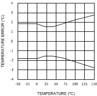 Figure 1. Temperature Error vs Temperature
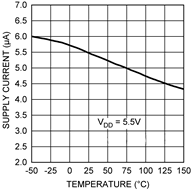 Figure 3. Supply Current vs Temperature
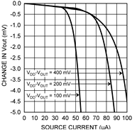 Figure 5. Load Regulation, Sourcing Current
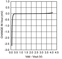 Figure 7. Change in Vout vs Overhead Voltage
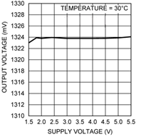 Figure 9. Output Voltage vs Supply Voltage
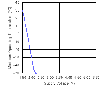 Figure 2. Minimum Operating Temperature vs
Supply Voltage
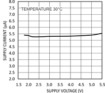 Figure 4. Supply Current vs Supply Voltage
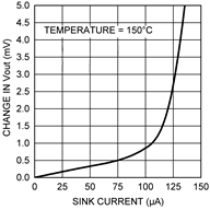 Figure 6. Load Regulation, Sinking Current
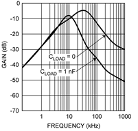 Figure 8. Supply-Noise Gain vs Frequency