DLPU018J October 2014 – June 2024 DLPC900
- 1
- Read This First
- 1Interface Protocol
-
2DLPC900 Control Commands
- 2.1 DLPC900 Status Commands
- 2.2 DLPC900 Firmware Programming Commands
- 2.3
Chipset Control Commands
- 2.3.1 Chipset Configuration Commands
- 2.3.2 Parallel Interface Configuration
- 2.3.3 Input Source Commands
- 2.3.4 Image Flip
- 2.3.5 IT6535 Power Mode
- 2.3.6 Gamma Configuration and Enable
- 2.3.7 LED Driver Commands
- 2.3.8 GPIO Commands
- 2.3.9 Pulse Width Modulated (PWM) Control
- 2.3.10 Batch File Commands
- 2.4 Display Mode Commands
- 2.5 Debug Mode Commands
- 3DLPC900 Fault Status
- 4Power-Up and Power-Down and Initialization Considerations
- 5Command Examples
- A Register Quick Reference
- B Batch File Command Descriptors
- C Revision History
3.2 DLPC900 FAULT_STATUS Interpretation
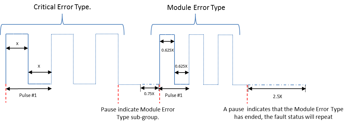
The format of the DLPC900 FAULT_STATUS signal is shown in Figure 3-1. The signal begins with a pulse, or pulses, indicating the critical error type. The number of critical error pulses indicates the critical error type as shown in Table 3-1. The critical error pulses are then followed by a short pause and one or more module error pulses. A longer pause follows the module error type, indicating repetition of the fault status sequence. In Table 3-1, the fault status can be interpreted by finding the status matching the number of critical error pulses followed by the number of module error pulses.
 Figure 3-1 DLPC900 FAULT_STATUS Format
| Number of Critical Error Pulses | Number of Module Error Pulses | Description |
|---|---|---|
| 1 - Main | 1 | Missing flash table signature |
| 2 - System | 2 | Mismatched controller SW configuration versions |
| 3 - Initialization | 4 | Error in first initialization of I2C |
| 7 | DMD Initialization error | |
| 8 | DMD/controller incompatibility fatal error |
For any combination of pulses not listed please contact TI for more information.