DLPU048E August 2016 – July 2024
- 1
- Trademarks
- 1 Introduction
- 2 Electrical Interface
- 3 Communication Protocol
- 4 System Operation
- 5 Application and Use-Cases
-
6 Tests and Diagnostics
- 6.1 Overview
- 6.2 Emergency Shutdown
- 6.3 Diagnostic Memory Interface
- 6.4
Test Descriptions
- 6.4.1
Periodic Tests
- 6.4.1.1 Video Source Loss Detection
- 6.4.1.2 Video Tell-Tale Checksum
- 6.4.1.3 Video Frame Counter Checksum
- 6.4.1.4 Average Picture Level
- 6.4.1.5 Loss of Ping Command
- 6.4.1.6 DLPC230-Q1 Processor Memory ECC
- 6.4.1.7 Flash Table Transport CRC
- 6.4.1.8 Frame Buffer Swap Watchdog
- 6.4.1.9 Sequencer Instruction Read Watchdog
- 6.4.1.10 DMD Reset Instruction Watchdog
- 6.4.1.11 DLPC230-Q1 System Voltage Monitor
- 6.4.1.12 DLPC230-Q1 DMD Voltage Monitor
- 6.4.1.13 DLPC230-Q1 TPS99000-Q1 Bandgap Monitor
- 6.4.1.14 DMD Temperature Monitor
- 6.4.1.15 DMD Clock Monitor
- 6.4.1.16 DMD High Speed Interface Training
- 6.4.1.17 DMD Low Speed Interface Test
- 6.4.1.18 TPS99000-Q1 DLPC230-Q1 Processor Watchdog (WD1)
- 6.4.1.19 TPS99000-Q1 DLPC230-Q1 Sequencer Watchdog (WD2)
- 6.4.1.20 TPS99000-Q1 Temperature Warning / Error
- 6.4.1.21 TPS99000-Q1 Clock Ratio Monitor
- 6.4.1.22 TPS99000-Q1 Register Password Lock
- 6.4.1.23 TPS99000-Q1 Register Checksum
- 6.4.1.24 Software Monitor Thread
- 6.4.2
Non-Periodic Tests
- 6.4.2.1 Execution Time
- 6.4.2.2 DLPC230-Q1 Front End Functional BIST (Main)
- 6.4.2.3 DLPC230-Q1 Back End Functional BIST (Main)
- 6.4.2.4 DLPC230-Q1 Memory BISTs (Main)
- 6.4.2.5 TPS99000-Q1 Interface Signal Connection Test (Main)
- 6.4.2.6 DMD Memory Test (Main)
- 6.4.2.7 Flash Data Verification (Boot/Main)
- 6.4.2.8 DLPC230-Q1 Boot ROM CRC (Boot)
- 6.4.2.9 DLPC230-Q1 Flash Table CRC (Boot)
- 6.4.2.10 DLPC230-Q1 Main Application CRC (Boot)
- 6.4.2.11 DLPC230-Q1 Command and Flash Interface Memory Test (Boot)
- 6.4.3 Interface Tests
- 6.4.1
Periodic Tests
-
7 Commands - Boot Application
- 7.1 Command Table
- 7.2
Command Definitions
- 7.2.1 System Reset - Write (00h)
- 7.2.2 Read Pre-Fetch - Write (01h)
- 7.2.3 Read Activate (02h)
- 7.2.4 System Software Version - Read (B0h)
- 7.2.5 Flash Device ID - Read (B1h)
- 7.2.6 Short Status - Read (C0h)
- 7.2.7 Error History - Read (C1h)
- 7.2.8 Clear Short Status Errors - Write (C2h)
- 7.2.9 Clear Error History - Write (C3h)
- 7.2.10 Flash Full Erase - Write (E0h)
- 7.2.11 Flash Write Data - Write (E1h)
- 7.2.12 Flash Verify Data - Write (E2h)
- 7.2.13 Flash Interface Rate - Write (E3h)
- 7.2.14 Flash Interface Rate - Read (E4h)
-
8 Commands - Main Application
- 8.1 Mode Availability
- 8.2
Command Definitions
- 8.2.1 System Reset - Write (00h)
- 8.2.2 Read Pre-Fetch - Write (01h)
- 8.2.3 Read Activate (02h)
- 8.2.4 Operating Mode - Write (03h)
- 8.2.5 Operating Mode - Read (04h)
- 8.2.6 Source Select - Write (05h)
- 8.2.7 Source Select - Read (06h)
- 8.2.8 Prepare for Source Change - Write (07h)
- 8.2.9 Display Image Orientation - Write (18h)
- 8.2.10 Display Image Orientation - Read (19h)
- 8.2.11 System Mode Select - Write (1Ch)
- 8.2.12 System Mode Select - Read (1Dh)
- 8.2.13 Execute Batch Command Set - Write (21h)
- 8.2.14 Execution Delay - Write (22h)
- 8.2.15 GPIO Configure - Write (23h)
- 8.2.16 GPIO Configure - Read (24h)
- 8.2.17 GPIO Outputs - Write (25h)
- 8.2.18 GPIO Outputs - Read (26h)
- 8.2.19 GPIO Reserved - Read (27h)
- 8.2.20 Execute Non-Periodic BIST - Write (28h)
- 8.2.21 External Video Checksum Control - Write (29h)
- 8.2.22 External Video Checksum Control - Read (2Ah)
- 8.2.23 External Video Checksum Settings - Write (2Bh)
- 8.2.24 External Video Checksum Settings - Read (2Ch)
- 8.2.25 DMD Socket Connectivity Test - Write (2Dh)
- 8.2.26 DMD Socket Connectivity Test - Read (2Eh)
- 8.2.27 Average Picture Level Control - Write (2Fh)
- 8.2.28 Average Picture Level Control - Read (30h)
- 8.2.29 Loss Of Ping Control - Write (33h)
- 8.2.30 Loss Of Ping Control - Read (34h)
- 8.2.31 PWM Temperature Management Enable - Write (35h)
- 8.2.32 PWM Temperature Management Enable - Read (36h)
- 8.2.33 PWM Temperature Management Source - Write (37h)
- 8.2.34 PWM Temperature Management Source - Read (38h)
- 8.2.35 PWM Temperature Management Duty Cycle - Read (39h)
- 8.2.36 Headlight Ping - Write (46h)
- 8.2.37 PWM Control - Write (47h)
- 8.2.38 PWM Control - Read (48h)
- 8.2.39 Illumination Transition Rate - Write (49h)
- 8.2.40 Illumination Transition Rate - Read (4Ah)
- 8.2.41 De-gamma Select - Write (54h)
- 8.2.42 De-gamma Select - Read (55h)
- 8.2.43 ADC Measurements - Read (5Ch)
- 8.2.44 ADC Single Measurement - Read (63h)
- 8.2.45 Illumination Bin Select - Write (70h)
- 8.2.46 Illumination Bin Select - Read (71h)
- 8.2.47 TPS99000-Q1 TIA1 Trims - Write (86h)
- 8.2.48 TPS99000-Q1 TIA1 Trims - Read (87h)
- 8.2.49 TPS99000-Q1 TIA1 Gain - Write (88h)
- 8.2.50 TPS99000-Q1 TIA1 Gain - Read (89h)
- 8.2.51 TPS99000-Q1 TIA1 Capacitance - Write (8Ah)
- 8.2.52 TPS99000-Q1 TIA1 Capacitance - Read (8Bh)
- 8.2.53 TPS99000-Q1 TIA1 Dark Offsets - Write (8Ch)
- 8.2.54 TPS99000-Q1 TIA1 Dark Offsets - Read (8Dh)
- 8.2.55 TPS99000-Q1 TIA1 Input Offsets - Write (8Eh)
- 8.2.56 TPS99000-Q1 TIA1 Input Offsets - Read (8Fh)
- 8.2.57 TPS99000-Q1 Drive Mode - Read (93h)
- 8.2.58 TPS99000-Q1 ADC Configuration - Write (94h)
- 8.2.59 TPS99000-Q1 ADC Configuration - Read (95h)
- 8.2.60 TPS99000-Q1 Illumination Sync Control - Write (96h)
- 8.2.61 TPS99000-Q1 Illumination Sync Control - Read (97h)
- 8.2.62 TPS99000-Q1 TIA2 Control - Write (98h)
- 8.2.63 TPS99000-Q1 TIA2 Control - Read (99h)
- 8.2.64 LED Drive Errors - Read (9Ah)
- 8.2.65 LED Drive Errors Clear - Write (9Bh)
- 8.2.66 TPS99000-Q1 Test Mux Select - Write (9Ch)
- 8.2.67 TPS99000-Q1 Test Mux Select - Read (9Dh)
- 8.2.68 Flash Data Type Select - Write (A0h)
- 8.2.69 Flash Erase Data - Write (A1h)
- 8.2.70 Flash Write Data - Write (A2h)
- 8.2.71 Flash Read Data - Read (A3h)
- 8.2.72 Flash Verify Data - Write (A4h)
- 8.2.73 Flash Block Count - Read (A5h)
- 8.2.74 Flash Block CRCs - Read (A6h)
- 8.2.75 Flash Structure Version - Read (A7h)
- 8.2.76 Flash Data Size - Read (A9h)
- 8.2.77 System Software Version - Read (B0h)
- 8.2.78 Flash Device ID - Read (B1h)
- 8.2.79 DLPC230-Q1 Device ID - Read (B2h)
- 8.2.80 DMD Device ID - Read (B3h)
- 8.2.81 TPS99000-Q1 Device ID - Read (B4h)
- 8.2.82 System Temperatures - Read (B5h)
- 8.2.83 Current Source Information - Read (B6h)
- 8.2.84 Current Display Information - Read (B8h)
- 8.2.85 System Information - Read (BAh)
- 8.2.86 Flash Interface Rate - Read (BBh)
- 8.2.87 Short Status - Read (C0h)
- 8.2.88 Error History - Read (C1h)
- 8.2.89 Clear Short Status Errors - Write (C2h)
- 8.2.90 Clear Error History - Write (C3h)
- 9 Commands - Diagnostic Interface
- 10Flash Configuration
- A Error Codes
- Revision History
5.5 Smooth Illumination Transition
The main application supports smooth transitions between sequences, or illumination bins, using digital contrast adjustments over a series of frames in order to attenuate the display brightness.
This feature prevents instantaneous changes in system brightness caused by large duty cycle differences in illumination bins.Figure 5-21 demonstrates an instantaneous brightness change that would occur without the use of this feature.
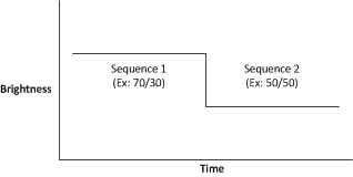 Figure 5-21 Instantaneous Duty Cycle Change
The following commands are used for this feature:
- Illumination Transition Rate - Specifies the number of frames over which the transition will occur. This effectively determines the time of transition based on the frame period multiplied by the number of frames. Changes to the brightness are calculated and applied each frame despite the step size allowed by this command.
- Illumination Bin Select - Specifies the illumination bin index that will be transitioned to. This command also triggers the start of the transition.
Note that this feature is only available while displaying external video or test patterns. It is not available while displaying splash images. While a splash image is displayed, the transition rate value is ignored and the commanded illumination bin will always be applied in one step.
When an Illumination Bin Select command is received, the main application begins transitioning brightness levels from the full digital brightness of the currently displayed illumination bin to the full digital brightness of the selected illumination bin. The main application uses the latest transition rate that was received prior to the start of the transition.
If an Illumination Bin Select command is received during an ongoing transition, the main application will terminate the ongoing transition by immediately switching to the last selected illumination bin. It will then start a new transition from the previously selected illumination bin to the newly selected illumination bin.
Figure 5-22 demonstrates the procedure that the main application performs to transition from a high brightness sequence to a low brightness sequence across 8 frames. Initially the system remains in the high brightness sequence and the digital contrast is decreased each frame so that the contrast-adjusted brightness of sequence 1 approaches the full-contrast brightness of sequence 2. On the last transition frame the contrast is returned to 1x and the sequence is transitioned to sequence 2. Figure 5-23 highlights the resulting total brightness of the combination of sequence and contrast brightness.
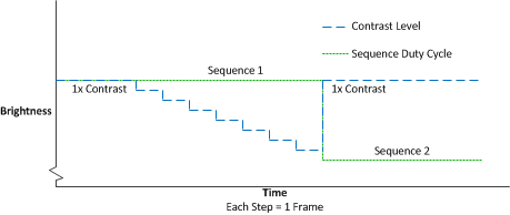 Figure 5-22 Duty Cycle Decrease
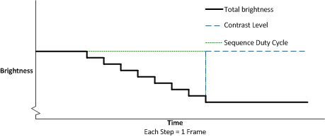 Figure 5-23 Duty Cycle Decrease Total Brightness
Figure 5-24 demonstrates the use of this function to transition from a low brightness sequence to a high brightness sequence across 8 frames. On the first transition frame, the sequence transitions to the high brightness sequence and the contrast is decreased to approximately match the low brightness sequence. Then the contrast is increased across the transition frames until the contrast returns to 1x. Figure 5-25 highlights the resulting total brightness of the combination of sequence and contrast brightness.
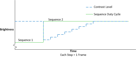 Figure 5-24 Duty Cycle Increase
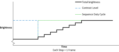 Figure 5-25 Duty Cycle Increase Total brightness