DLPU101D December 2020 – July 2024 DLPC900
- 1
- Trademarks
- Read This First
- 1 About This Guide
- 2 Related Documentation from Texas Instruments
- 3 If You Need Assistance
- 4 DLP LightCrafter Single DLPC900 EVM Overview
- 5 Quick Start
-
6 Operating the
DLP LightCrafter Single DLPC900 EVM
- 6.1 DLP LightCrafter Single DLPC900 Control Software
- 6.2 PC Software
- 6.3 System Common Controls
- 6.4 System Settings
- 6.5 Video Mode
- 6.6
Pattern Modes
- 6.6.1 Menu Bar
- 6.6.2 Creating a Pattern Sequence in Pattern On-The-Fly Mode
- 6.6.3 Creating a Pattern Sequence in Pre-Stored Pattern Mode
- 6.6.4 Reordering a Pattern Sequence using the Edit LUT Feature
- 6.6.5 Creating a Pattern Sequence in Video Pattern Mode
- 6.6.6 Creating a Pattern Sequence With DMD Block Load
- 6.6.7 Pattern Settings
- 6.7 Batch Files
- 6.8 Peripherals
- 6.9 Firmware
- 6.10 Flash Device Parameters
- 6.11 JTAG Flash Programming
- 6.12 Programming an EDID
- 7 Connectors
- 8 Power Supply Requirements
- 9 Safety
- 10Revision History
6.6.5 Creating a Pattern Sequence in Video Pattern Mode
Creating a Video Pattern Mode sequence is also similar to Pattern On-The-Fly Mode. The difference is that the patterns are streamed from the input video source. The user must create the video images and then input them through the RGB parallel interface. The input video source vertical sync is used as the triggering mechanism. The input video source must be stable and locked and continuously being applied, otherwise the firmware detects that the source was lost and a solid curtain is displayed. While the video source is stable and locked, the status box for Locked to External Source remains checked.
Follow these steps to create a Video Pattern Mode sequence.
- Make sure the EVM is powered up and operating correctly, and the Connected radio-button is lit green.
- Select Video Mode from the Operating Mode group box, and then select the HDMI radio-button from the IT6535 Receiver group box and finally click the Set button. (Select the DisplayPort radio-button if using this input connector). The Locked to External Source status box is checked after a few seconds.
- Verify the video source is displayed. If no video source is displayed, then make sure the PC or host is supplying the correct resolution and frame rate. See Video Support for video support.
- Select Video Pattern Mode from the Operating Mode group box, and then click the Pattern Design button so that the large black panel is displayed as shown in Figure 6-6.
- Click the Add Pattern button on the Menu bar and add 3 patterns. (Hover over buttons in the Menu bar to see the tool tip).
- Click the Select All Patterns button to select all images.
- Set exposure time to 1215µs and dark time to 0µs.
- Select the first image and select a bit depth of 2, start bit G0, and color Green.
- Select the second image and select a bit depth of 4, start bit R0, and color Red.
- Select the third image and select a bit depth of 3, start bit B0, and color Blue
- Click the Select All Patterns button.
- Remove the check from the Frame Change box.
- Select pattern 0 (first pattern) only and check the Frame Change box.
- Click the Update LUT button.
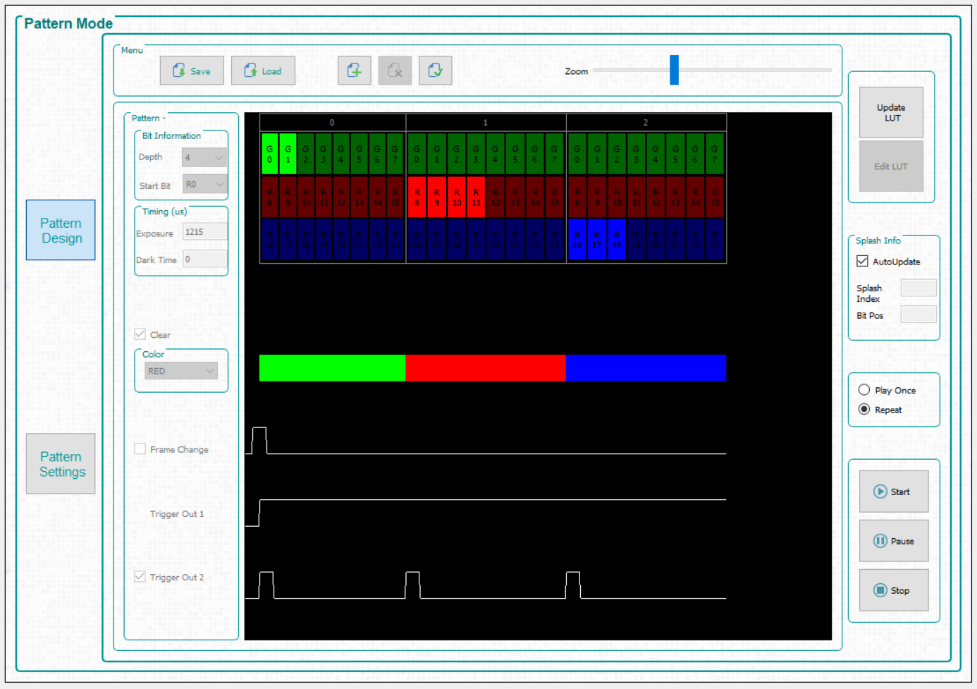
- Click the Start button to run the sequence. The system displays a green 2-bit sequence based on G0 - G1 for 1215μs, a red 4-bit sequence based on R0 - R3 for 1215μs, and a blue 3-bit sequence based on B0 - B2 for 1215μs with the remainder of the video frame time dark. This sequence repeats every frame with the new video data for that frame.
- Click the Stop button to end this example.
See Figure 6-14 after all settings have been applied.
 Figure 6-14 Video
Pattern Mode