DLPU101D December 2020 – July 2024 DLPC900
- 1
- Trademarks
- Read This First
- 1 About This Guide
- 2 Related Documentation from Texas Instruments
- 3 If You Need Assistance
- 4 DLP LightCrafter Single DLPC900 EVM Overview
- 5 Quick Start
-
6 Operating the
DLP LightCrafter Single DLPC900 EVM
- 6.1 DLP LightCrafter Single DLPC900 Control Software
- 6.2 PC Software
- 6.3 System Common Controls
- 6.4 System Settings
- 6.5 Video Mode
- 6.6
Pattern Modes
- 6.6.1 Menu Bar
- 6.6.2 Creating a Pattern Sequence in Pattern On-The-Fly Mode
- 6.6.3 Creating a Pattern Sequence in Pre-Stored Pattern Mode
- 6.6.4 Reordering a Pattern Sequence using the Edit LUT Feature
- 6.6.5 Creating a Pattern Sequence in Video Pattern Mode
- 6.6.6 Creating a Pattern Sequence With DMD Block Load
- 6.6.7 Pattern Settings
- 6.7 Batch Files
- 6.8 Peripherals
- 6.9 Firmware
- 6.10 Flash Device Parameters
- 6.11 JTAG Flash Programming
- 6.12 Programming an EDID
- 7 Connectors
- 8 Power Supply Requirements
- 9 Safety
- 10Revision History
6.6.4 Reordering a Pattern Sequence using the Edit LUT Feature
The Edit LUT feature is only available in Pre-Stored Pattern Mode and Pattern On-The-Fly Mode when using GUI 4.0 or later in conjunction with Firmware 5.0 or later. This feature allows the user to manipulate the pattern display sequence without having to reload or change any data in the DLPC900 memory. The Edit LUT button appears on the right hand side of the Pattern Mode tab after adding patterns as described in Section 6.6.2.
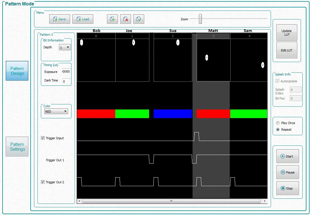
 Figure 6-11 Pattern Design Example
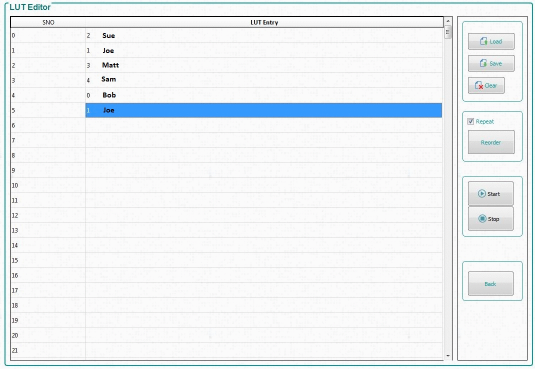
The LUT Editor panel is shown in Figure 6-12 where the column labeled SNO (for example, sequence number) represents the pattern display slot numbers according to the order set (after clicking Update LUT) in the Pattern Design tab as shown in Figure 6-11. The user can then reorder those patterns by either manually entering the pattern number of choice into a row in the LUT entry column or loading a text file beginning with the word Reorder followed by the desired numerical pattern slots as shown in Figure 6-13.
 Figure 6-12 LUT Editor Panel
The following steps detail an example using the Edit LUT feature with five patterns in Pattern On-The-Fly-Mode:
- By following the steps similar to Section 6.6.2, load five patterns in Pattern On-The-Fly-Mode as shown in Figure 6-11.
- Set the exposure time to 1000000μs for ease of viewing.
- Set an input trigger on Pattern 3 by checking the Trigger Input box.
- Set all other user desired pattern property settings.
- Click the Update LUT button and wait for all patterns to be uploaded to the EVM.
- Click the Start button to view the pattern display order.
- Click the Edit LUT button to open the LUT Editor panel as shown in Figure 6-12. This panel initially opens with an empty LUT Entry column.
- To reorder the patterns, enter a 2 in LUT Entry row 1, and subsequently a 1, 3, 4, 0, and 1 as shown in Figure 6-12 .
- Click the Stop button to stop the pattern sequence even if not currently running.
- Check the Repeat box for display repetition of the new pattern sequence and then click the Reorder button.
- Click the Start button to view the new pattern display order.
- Click the Save button to save the new pattern sequence as a text file for later use. Name the file Reorderexample.txt and save in a directory of choice.
- Browse to wherever the text file was saved, and open the file in a text editor program as shown in Figure 6-13.
- Notice at the top of the text file is the word Reorder which is required to successfully load a reorder file in the GUI. If desired, swap any of the pattern numbers to create a new pattern sequence and save the file.
- Click the Load button and browse for Reorderexample.txt.
- Click the Start button to view the new pattern display order.
- Click the Stop button to stop the pattern sequence.
- Click the Back button to return to the Pattern Mode tab.
When using the GUI interface, each pattern carries several items of information corresponding to the slot that was inserted in the original LUT order. Therefore, when reordering a pattern to a different slot in the LUT, the LUT retains the original assigned bit information, timing (exposure and dark time), LED color, and trigger information and not the information that is located in the reassigned slot in the LUT. For example, if pattern 3 contains a trigger input to begin the user’s execution in Figure 6-11 and is reordered to slot 2 as shown in Figure 6-12, then the trigger input is now located at slot 3 in the LUT rather than slot 0.
In Pre-Stored Pattern Mode, reordering the LUT does not change the pattern locations as the LUT does in Pattern On-The-Fly Mode. Only the requested bit information, timing, color, and trigger information are be reordered based on the user’s updated LUT. However, users can manipulate the pattern information after reordering the sequence by manually editing the batch file commands uploaded to the EVM rather than using the GUI.
 Figure 6-13 Reorder Example
TI recommends to understand the Edit LUT feature by giving names to the patterns, as shown above the patterns in Figure 6-11, and treating them as the batting order in a baseball game making easier to picture the distinction between the slot order numbers in the SNO column (the new batting order) and the patterns that are inserted into the LUT Entry column (the batters). For example, Bob retains his batting statistics independent of his batting position (for example, bit information, timing, color, trigger), so if he originally bats first (slot 0 in Figure 6-11) but is moved to fifth in the new batting order (reorder LUT entry 4 in Figure 6-12) he retains all of his properties. The only difference is that now he does not bat (for example, is not displayed) until after the four batters (patterns) preceding him (Sue, Joe, Matt, and Sam). Notice also that in our example Joe bats twice in the new batting order (SNO 2 and 5). There is only one Joe, who bats twice in the new batting order. In the same way, a pattern in the original pattern list can be displayed in many positions in the reordered display LUT, without adding or removing any patterns in DLPC900 memory. Therefore, in terms of the system memory, the LUT is only changed when using the Update LUT feature but never when using the Edit LUT (reorder) feature in the Figure 6-11.