DLPU108 May 2022 DLP5532-Q1
2.4 Connecting EVM to the DLPC230-Q1 Control Program
- Start the DLPC230-Q1 Control Program Lite.
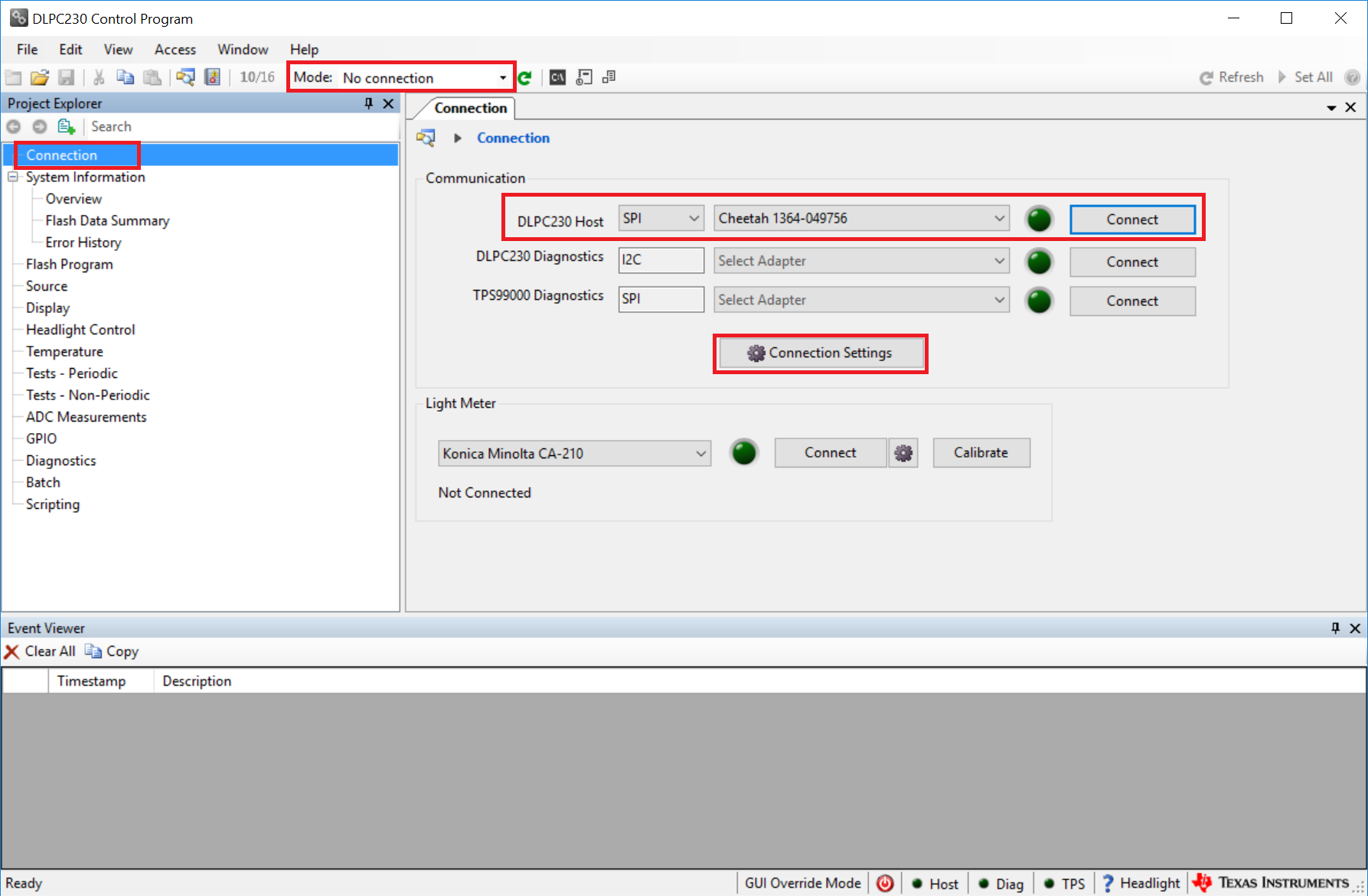
- On the connection page, set the DLPC230-Q1 Host to SPI and
select the Cheetah from the drop-down menu (see Figure 2-4). Note, the Cheetah must be connected to a computer with USB cable for it to
show up in the drop-down menu.
 Figure 2-4 Connecting to the
DLPC230-Q1 Using the DLPC230-Q1 Automotive Control Program
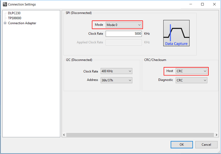
 - Select Connection Settings to confirm
the SPI configuration shown in Figure 2-5 matches the controller PCB switch settings described in Table 1-3. Specifically, SPI mode and CRC/Checksum can vary based on switch settings.
When configuration is complete, press OK.
 Figure 2-5 DLPC230-Q1 Automotive
Control Program Communication Settings
 - Click the Connect button. The green circle next to the Connect button then lights up to indicate that connection was successful to the Cheetah Adapter.