DLPU109A May 2021 – September 2024
2.2.1 DLPC7540EVM Connections
The switches and connectors with the respective locations are shown in Figure 2-1. Note that neither cables nor the power supply are included with the module.
 Figure 2-1 DLPC7540EVM Formatter Board Connectors
Formatter Board Connectors
- J2 – Micro-USB
- J3 – V-By-One Input
- J4 – 12V Fan
- J5 – 12V Fan
- J6 – Test Points Header
- J7 – DMD HSSI0 Flex Cable Connector
- J8 – 12V Fan (Heatsink)
- J9 – Hold Bootloader
- J10 – DMD HSSI1 Flex Cable Connector
- J12 – I2C1 Bus
- J16 – I2C0 Bus
- J17 – Actuator PWM Interface
- J20 – JTAG Boundary Scan
- J67 - 5V Enable for V-By-One Front-end Board
- J102 - RS232
- J120 - Actuator DAC Driver A/B
- J121 - Actuator DAC Driver C/D
- J122 - Actuator DAC Driver Enable
- J529 - 12V Input
- J536 - I2C2 Bus
- SW1 – Projector On Switch
- SW5 - Main Power Switch
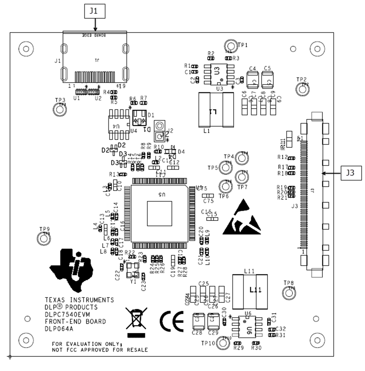
 Figure 2-2 DLPC7540EVM Front-end Board Connectors
Front-end Board Connectors
- J1 - HDMI Input
- J3 - V-By-One Input